What is Drawn != To What Works…Sometimes
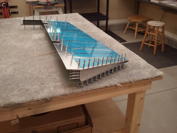
In the spirit of doing something little any chance you can, I decided to work a little on the elevator trim servo/mount/cover tonight. I am using the electric trim option as I love it in the CAP planes I fly. Not to mention, I will more than likely add the auto trim feature in conjunction with the auto pilot I want to install too so electric trim is required. It may be overkill, but heck…I am building MY plane.
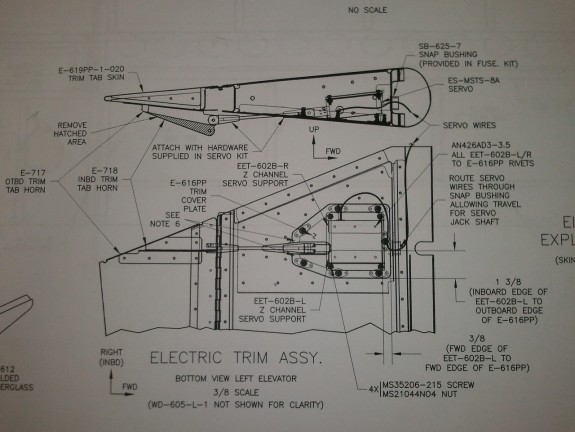
So I studied the plans that outlined how and what I needed to do to mount the trim servo. I made certain that I remembered that I was looking at the outside of the cover/inspection plate in the plans. I did not want to accidentally measure where to mount things by reading the dimensions relative to the outside and mark them on the inside wrong. As you can see from the plans, you are to measure from the outboard side of the cover 1 3/8″ in and 3/8″ in from the forward edge. This is then where you put the inboard forward edge of the left servo bracket (EET-602B-L).
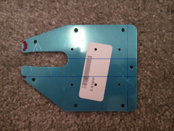
I grabbed my ruler and then began to mark the cover with the measurements outlined.
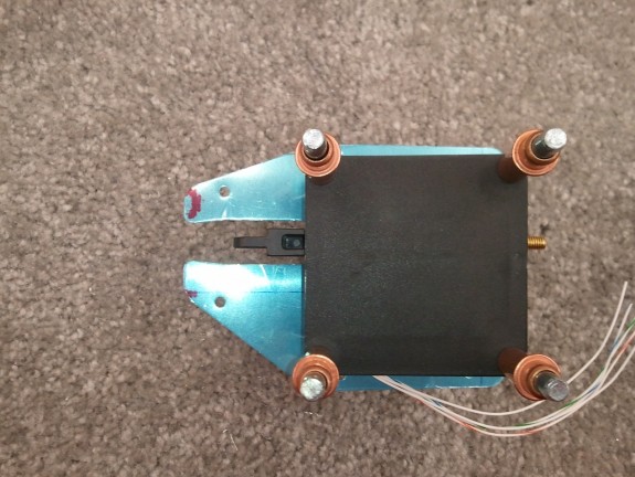
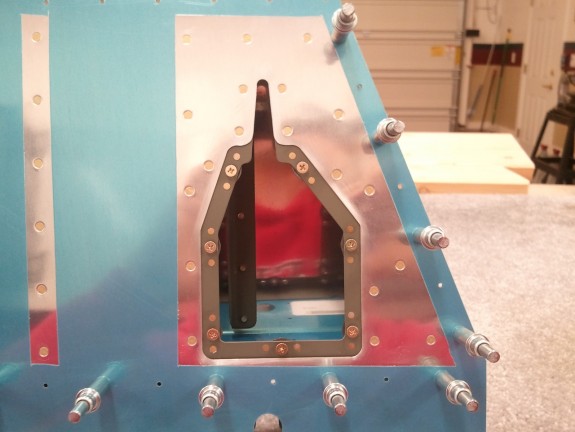
You can see here that the “upper” line is the line represented in the plans that should be 1 3/8″ from the edge. Basically, set the plate face down on the plans and then flip it up so it is a mirror image. Right off the bat it was clear that this was not right. The line seems to be nearly centered in the slot for the servo arm. Referencing the plans again showed it really should be offset a bit. Clecoing the servo to both mounting brackets and setting it on the cover confirmed this as well, the output arm of the servo was not centered in the slot as the plans show.
I scratched my head a bit and thought…what if they really meant 1 3/8″ from the other edge and just marked it wrong on the plans? With all the flipping and translation to the part you have to do with the drawing, maybe they made a mistake…though unlikely. I also did a search on vansairforce.net to see if others were having issues with this drawing as well. The search returned a few replies that led me to believe the unlikely was true.
What the heck, I have not drilled anything yet, so I drew another line from the other edge and lined up the inside edge of the EET-602B-R and interestingly enough, the servo output was dang close to center in the slot. I think the draftsman did actually reverse the part.
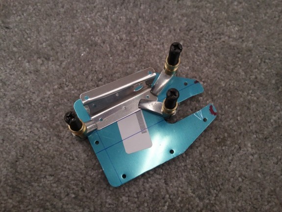
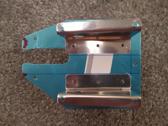
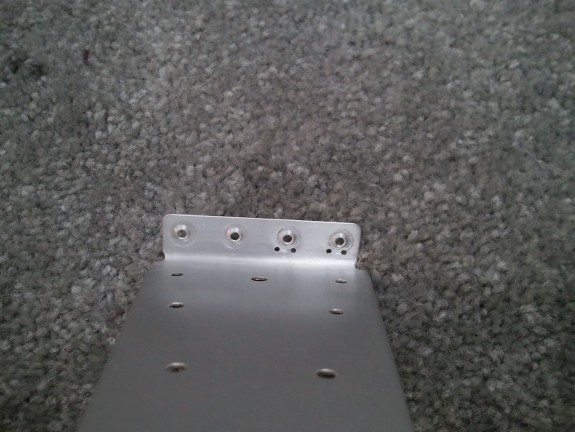
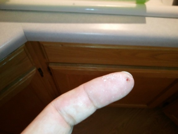
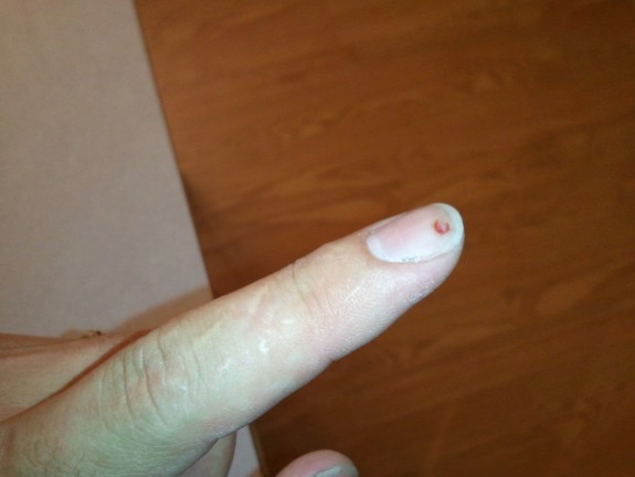
With the bracket confusion now settled and the correct orientation determined, I clamped the EET-602B-R to E-616PP. Having learned to not back a hole you are drilling with your finger, I used block of wood behind the hole I was drilling and match drilled the bracket to the cover, clecoing as I went. Once that was done, I clecoed the servo and other bracket back on and then clamped the EET-602B-L on and repeated the process.
Once complete and both are clecoed on, you can see that the EET-602B-L reference line as outlined in the drawing is indeed off by about 1/16 of an inch. It may not seem like a lot, but it will make a big difference if you were to follow the plans. I have read that some have just followed the plans and had to widen the slot for the arm, and others just replace the cover and do it again by eye. I recommend however you simply measure from the other side and line up the opposite mount bracket and you should be OK.
All said and done, the servo output shaft is right where it should be. The last problem is that the aft two rivets that rivet the servo mount brackets to the cover may actually cause the servo to sit proud of the mounts because the shop head/dimples may contact the case. I may countersink the last two to avoid this. I have heard that some have made shims for the servo while others smash the heads a little more to clear the servo. Neither seems correct to me as one moves the servo alignment and the other weakens the assembly, granted, not by much. Stay tuned for the solution.

