Rudder Complete…for Now
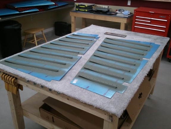
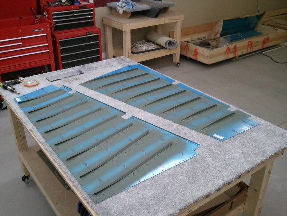
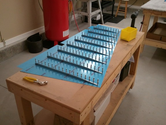
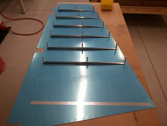
Once the trailing edge was dry from the tank sealant applied Thursday, it was time to close it up. I was still a little nervous about the double flush riveting that had to be done. The manual does a good job describing the procedure, but it is still somewhat daunting. I decided early on that I wanted to alternate the manufactured and shop heads side to side for balance. May seem trivial, but I wanted a more symmetric appearance from side to side.
I pulled off the two angles and clecos and was pleased to see a straight trailing edge all glued up. I had a bit of cleanup to do with MEK to get the oozed sealant off the skins. There was a bit in each hole as well. I simply ran a #40 bit by hand through the holes to get the sealant to break at the edges of the holes and pulled out the little ball. Some of the dimples were filled so I lightly ran a countersink bit in them and it cleared it right out.
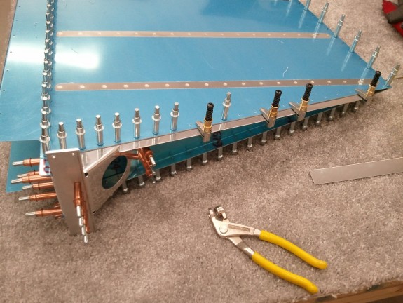
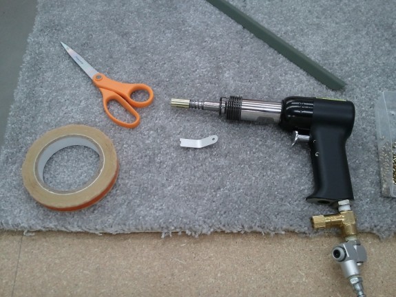
Now that it was all cleaned out/off, I set a rivet in every other hole and taped them in. I then flipped the rudder over and made my first mistake. I put my mushroom set in the gun and started to “half set” the tails starting from the middle of the rudder and working my way out alternating the sides from center. The mistake was using the mushroom set. It is simply the wrong set to use at this point. About halfway through setting these, the set slipped and I dented the skin near the spot where the skin and the AEX wedge meet underneath with the heal of the mushroom set. At this point I should have realized I was not using the right set. I did it once more and then figured out what was wrong. Filler at paint will hide the dents just fine but it was still aggravating.
Once I realized I should have been using my back rivet set to “half set” the tails, all started to flow. I simply angled the set enough to push the tail into the center of the dimples and then rotated the set to be parallel to the skin. The head of the set never came close to the skin…duh! I got all the shop heads set, and then flipped the rudder over. NOW you put the mushroom set in and smack the manufactured heads over the back rivet plate. After a few…I realized I was getting it…too bad it took some dents to get there.
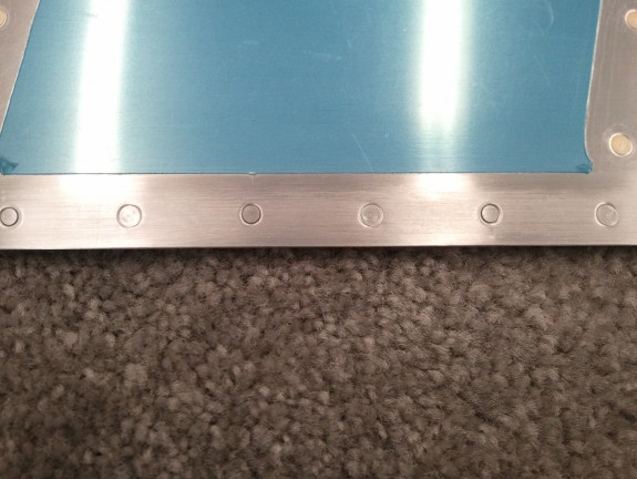
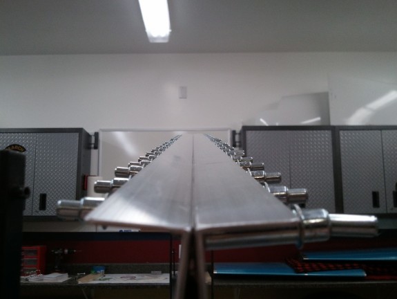
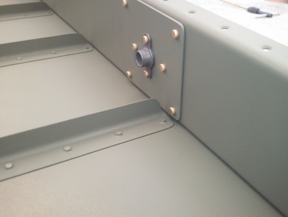
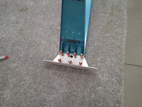
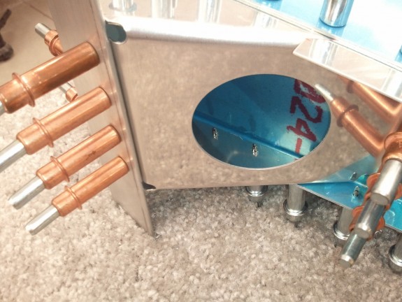
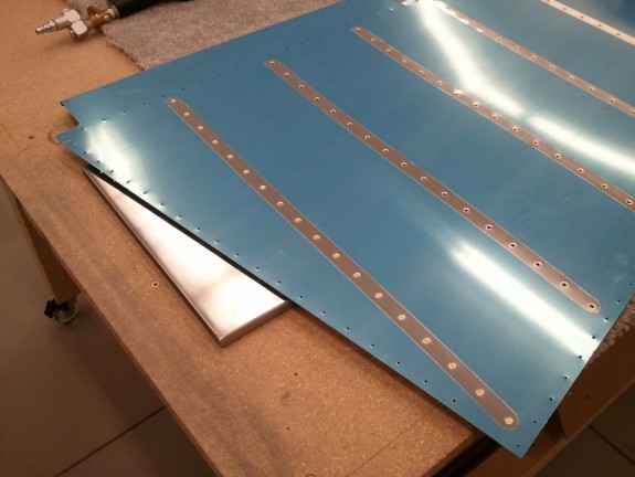
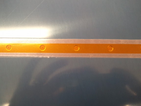
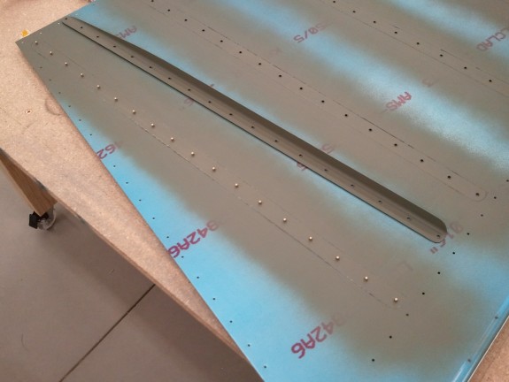
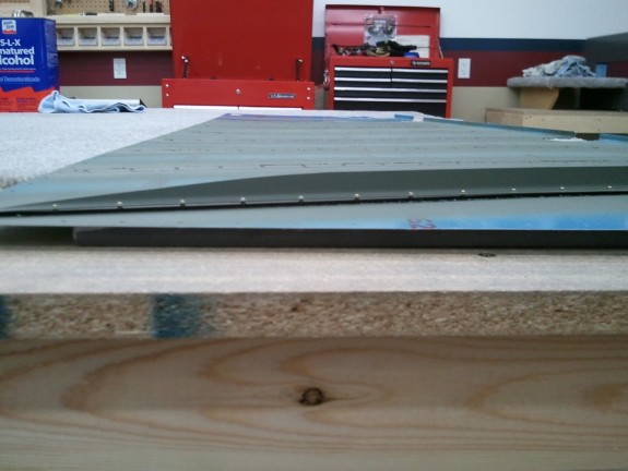
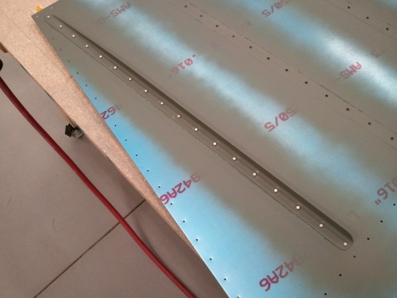
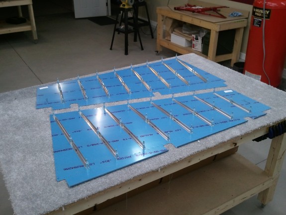
Once all the rivets were smashed into the dimples completely, I repeated the process with the remaining holes with the manufactured heads on the same side of the “acorns in the dimples” now complete. You can see the result above. They look great and the trailing edge came out straight and within tolerance per the manual.
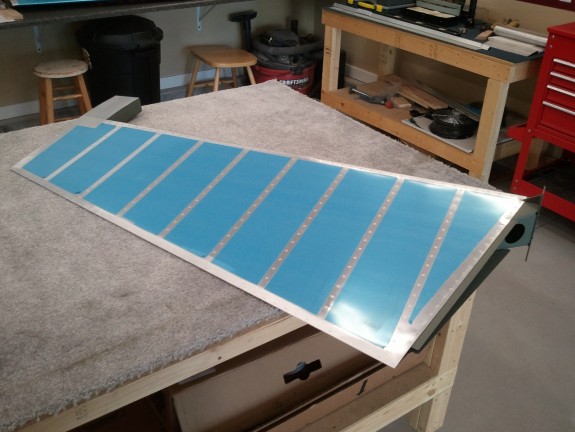
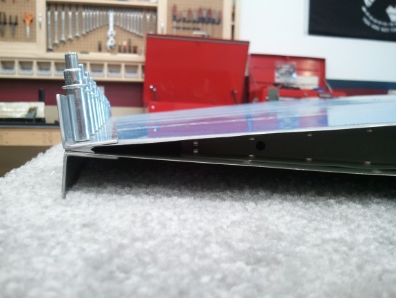
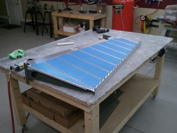
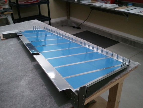
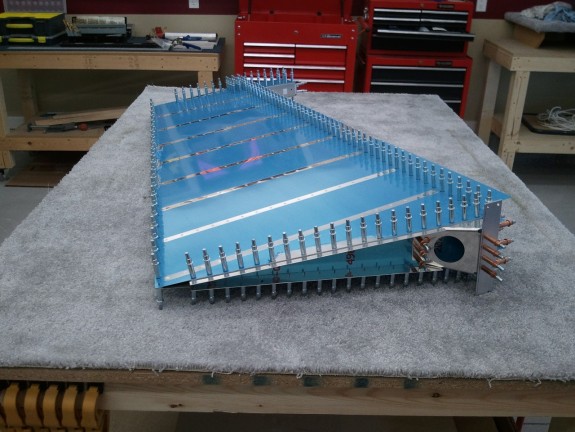
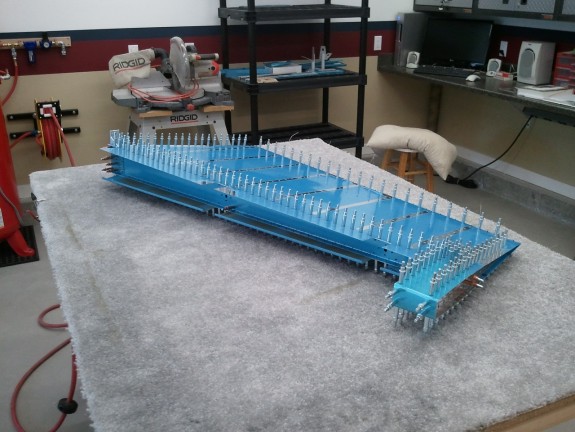
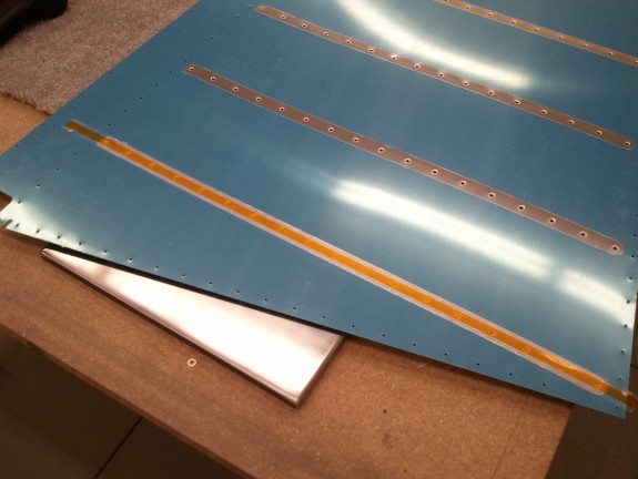
Here is an overview shot of the rudder trailing edge complete. Nice and sharp and pretty straight. The next step was to then roll the leading edges to complete the assembly.
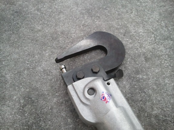
I wanted to get a nice clean joint along the leading edge. Prior to rolling them, I decided to use a nifty tool I got from Cleaveland Tool that forms the edge of material that will be lapped over another sheet. Basically, it bends a very gentle lip on the edge of the sheet so that when the two sheets are overlapped and then riveted, it makes a nice tight joint. I learned another valuable lesson here. NEVER try a tool for the first time on an assembly. Either mine is defective, or I do not know how to use it…but I mangled up one of the tabs on the top overlapping skin of the leading edge portion. Basically, the roller of the tool with the lip on it did not ride the edge as it is designed, but it rolled past the edge of the tab and made a mess of that edge. I was simply deflated. NEVER EVER use a tool on a part until you have mastered its use. I was able to get most of the mess out by using a wooden block with a slot cut in it about 1/4″ deep to straighten out the mess the tool made and then hand bend a flange in the tab…but the Cleaveland tool had stretched the metal in some places that was simply not going to be 100%. Aggravating to say the least. I will be practicing a TON more on scrap with this tool before it ever touches my plane again. The video below makes it look easy…mine did not work out so well.
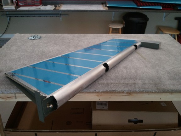
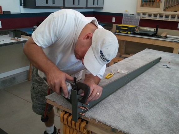
After the skins were rolled, I simply clecoed them together and worked the radius a little more by hand. Then I match drilled and deburred the holes to a #30. Here is where the mangled tab edge created earlier showed its problems. Many builders report little puckers between the rivets when the finish this part. Mine did the same on the center tabs. If I had not had issues with the edge forming tool, I think I could have had a really nice overlap on the center section. Needless to say, where the metal was stretched by the tool, my puckers are not pretty. The upper and lower overlaps look pretty good. Either way, this particular area will NEVER be seen unless the rudder is removed from the plane. Even at full deflection, you cannot see it, so…I am calling it good enough for now. At 200 mph and FL20, it will not make a difference in flight. If it REALLY bothers me when the plane is ready for paint, I may build another rudder. Unlikely as this one looks good otherwise and is very structurally sound.
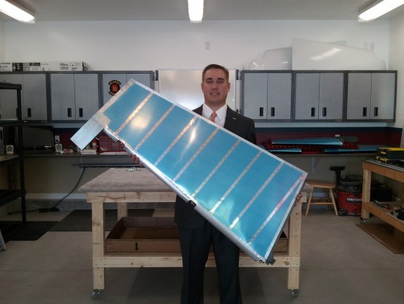
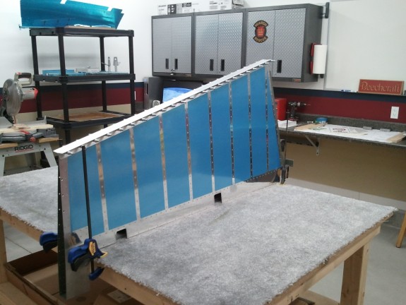
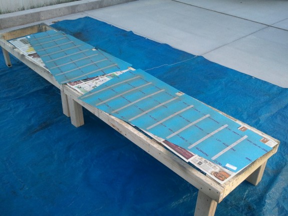
We end the day with a glory shot. I had a conference meeting to attend after the build session and my lovely photographer was busy all day. So I convinced her to take a picture of the finished rudder right before I left. I think I may have the record for the most cleaned up glamor/status shot out there. All in all a good day. The fiberglass tips are all that remain. Time to get started on the elevators now.

