Archive

Archive for the ‘Tanks’ Category

Right Tank Installed and Top Skins Fit for Final Riveting

June 24th, 2017 No comments

Right tank mounted after testing LEAK FREE and top skins mounted for final riveting

A few weeks ago, I was able to finally pressure test the right tank for leaks. While it didn’t go as smoothly as the left, it still came out very positive. I had also previously primed the dimpled right top skins and they were getting in the way on the bench. So after taking care of some chores this morning, I determined to get some loose ends tied up and be ready to rivet the top skins on soon.

I first had to rivet the remaining leading edge rib to spar interfaces. Since I am largely doing this project solo, I resorted to using Cherry Max rivets for the two most central ribs. This left the two inboard and two outboard ribs to finish. I am not a fan of the offset rivet set that’s required nor the contortions to hold the bucking bar…but I got it done. It took more time than I first anticipated, and my body reminded me of its limits, but each was set, and set OK.

Once that was done, I went about installing the right tank to the wing. There’s something VERY gratifying about installing that big of a part to an assembly. I torqued the bolts appropriately and then also double checked the left tank bolts (it’s been a while…so it was prudent). I reached into the tool cabinet for some torque seal/mark, only to find that all my tubes had dried out. I really need to work more consistently on this project. I’ll place an order for some more and mark each of these bolts.

Once mounted, it was time to reinstall the primed top skins in place and ready them for riveting. I will be double checking for twist, and then one of my kiddos and I will go to it. Can’t wait to move on again. The poor fuselage kit is aching to be worked on.

Categories: Tanks

Left Tank Pressure Testing

June 17th, 2016 No comments

Pressure testing left tank

So I decided to use the manometer method to test the tanks for leaks. Word of warning, this method is dang sensitive. Slight temperature and pressure changes throughout the day can have you chasing your tail and creating false alarms. I see the wisdom in balloon method…as it gives a good indication of success without giving the builder a scare if he’s an over thinker. The other way is to make sure you have an accurate means of measuring all the other factors at the same time as looking at the column of water. It’s repetitive math, but it can give you a dang accurate look at your success.

Column of water is showing stable pressure

As it stands, my column of water shows a leak free tank after 4 days since starting the experiment. 1 down, 1 to go.

Categories: Tanks

And…They’re Done!

June 4th, 2016 No comments
Right Done Done!

Right Done Done!

Had another GREAT day getting the last of the last of the sealant tasks for the tanks done. As you can see above, I sealed the right tank pickup and cover plate on. I opted to NOT use the cork gasket as many other builders have done. I also replaced the standard 8/32 x 1/” Phillips head screws with Stainless Allen cap screws and washers instead. IF I ever need to remove these covers while the tank is mounted to the air frame/wings, I can use a hex key rather than a screw driver. A provision that I hope to never have to use, but one that was cheap and easy to do, just in case.

That's All Folks!

That’s All Folks!

Here you can see both, side by side, fully sealed. I did make a good fillet around each screw head with sealant after dipping each screw in sealant before installing them. Just extra hopeful leak free insurance. I also did a little fillet around the BNC connectors for the capacitive fuel senders, also just in case.

Left Tank Cover Plate Done

Left Tank Cover Plate Done

Here is a close up. The sealant is about the nastiest stuff made to man…other than used baby diaper deposits. I plan to let these sit for a week, then I’ll be able to pressure/leak test. If all goes well, we may be able to claim success. I was able to get these done about mid-day…which meant I could now move on. I was able to do just that. Until the pressure/leak check, I’m moving back over to the Wings. Hears hoping…no more sealant for a LONG time!


Categories: Tanks

Tanks Finally Sealed…Almost

May 30th, 2016 No comments
Left rear baffle

Left rear baffle

HAPPY MEMORIAL DAY! What a FANTASTIC day it was for me. I closed up both tanks today. I am SOOO close to being done with this nasty, horrible, and obnoxious sealant. Started off with the right tank. Cleaned every surface I could think of with MEK. I had made a good effort to scuff the baffle a bit more aggressively in the places where the sealant was going to mate with the rest of the tank on the Saturday prior. Once all the parts were clean, I committed to just getting at it. I was able to borrow my fellow builder and all around good guy Todd’s pneumatic sealant gun that works with the sealant cartridges I have been using. I do have a mechanical version (much like a caulking gun), but his lays the sealant soooo nice.

With tools, gloves, clecos, and anything/everything one needs to get messy with sealant, I went right at it. First I laid a nice bead of sealant along the forward edge of the rivet line on the top and bottom sides of the skin. Next up was a healthy glob at all the corners. I then laid a bead on the inside edges of the end ribs, then finally buttered each of the end flanges of the interior ribs. At this point, you simply slide the rear baffle down into place, squeegeeing the bead of sealant down as the baffle seats in its final location. It gives a nice satisfying squishy feel as you seat it. You then cleco each hole in the skin to baffle interfaces.

From here, it is now time to use your ground off or close tolerance pop rivet gun. Remember how I thought painting the freshly modified nose was a good idea? It wasn’t after all. Paint simply chipped off as I was using it. None the less, it was still effective in getting the job done. You first need to rivet the baffle to the top and bottom holes on each of the interior ribs with some cool little closed end rivets. The mandrel does not go all the way through on these, but is captured inside the actual body of the rivet. This solves the problem of at least fuel leaking through the rivet, but does not really solve the problem of it possibly leaking around the rivet. Van’s tells you to “twirl the rivet” in sealant before inserting…and while that coats the side of the rivet with some sealant, the holes have to remove most of it. None the less…as the rivet expands, with the coating of sealant, the hope is, that it creates a “fuel tight” closure to that hole.

Once you’ve done the top and bottom holes, I then proceeded to attach the “Z” brackets to the baffle/ribs. This is done with the same closed end rivets, but of a longer length. Van’s warns you to make sure that the orientation is correct, and for good reason…because once they are on, they are on. The modified pop rivet gun worked great. With all the “Z” brackets now on, you move on to riveting the skins to the baffle. My pneumatic squeezer made quick work of this task.

Hopefully a good enough bead

Hopefully a good enough bead

Once all the riveting was done, I added some more sealant to the outside of the corners to build them up a bit. I also likely put sealant on places that didn’t need it, but what the heck…just in case. In looking at as much as I can see of the beads done, they look pretty good so far. I am going to borrow a borescope and see if I can get a real good look all the way through, but if the beads look like the above photo all the way through, I think I will be OK. Once all this was done, I repeated the process on with the left tank.

Both now curing

Both now curing

Here’s the right tank, in all it’s sealed up glory. All I have left is to install the cover plate(s) and then pressure test. So glad to have the major parts done at this point. Fingers crossed that they are leak free and I can move on to just metal to metal joining.

P.S. I HATE TANK SEALANT!

Categories: Tanks

Sealing the Fuel Pickup Tubes

May 28th, 2016 No comments
Done and Curing

Done and Curing

Spent the afternoon, after running all over town to find some “crow feet” wrench adapters (DON’T get me started on Sears!) and other lawn care items, sealing up the last of the tank penetrations. I used a cartridge of B 1/2 and made quick work of the left and right pickup tubes and anti rotation brackets. I also torqued the vent and return line nuts (with the crow foot adapter and torque wrench).

Right Tank Fitting Overkill

Right Tank Fitting Overkill

I always wondered how folks were insuring that the nuts on the vent lines, and by virtue my return lines, couldn’t back off. Technically, they are inside the tank and other than losing the high point of the fuel tank on the vent line, the risk is minimal if they did back off, but still…I didn’t like the idea of lines “potentially” coming off over time in a relatively sealed up area of the plane. So…once I had the pickup tube done…I simply gooped up the nuts with some sealant and called it good.

Left Tank Fitting Overkill

Left Tank Fitting Overkill

Hopefully, I never have to get them off…ever. I don’t think I would be able without some serious work. That said, I don’t think I have to worry about them ever coming off when I don’t want them to. I’ve done cleaner sealant work, but I have also done worse. I’m just glad I am closer to not having to deal with sealant any more.

Categories: Tanks

The Final Tank Tool

May 25th, 2016 No comments

[Update 5/30/2016…Don’t paint the head. It didn’t stick as well as I thought when using it on the “Z” brackets]

Old is New

Old is New

One of the tools that one requires to properly finish the fuel tanks is a close quarter pop rivet tool (which are becoming harder to find these days) or even using a close quarter wedge like Cleaveland Tool sells to set the fuel tank rear baffle “Z” bracket pop rivets in place. If neither of these are desirable, you can always grind down the nose of a regular pop rivet tool. That’s exactly what I decided to do. Interestingly enough, I had a spare Stanley MR77C due to me thinking I ruined it once, so I bought another only to discover later the original was OK. So, having two, I committed to converting the “old” one to a close quarter version today.

Modified and Ready for Action

Modified and Ready for Action

All I did was grind away at the nose, little by little, until I felt I had the clearance needed to get right on the head of the rivets and adequate clearance from the “Z” bracket side. I made sure to do this while the handles were in the “open” position so that the pulling mandrel was seated in the start or bottomed out part of the nose. Once ground down to my satisfaction, I disassembled the head and cleaned up all the grinder marks to a smooth finish on both the head and the pulling mandrel. Most would call it good at this point…but not me. I decided to spray paint the now paint free surfaces of the head to protect them, which quickly turned into painting the entire head. I actually chose a contrasting color, so as it hangs in the shop next to the unmodified version, I can quickly know which is which. A little overkill to some. Oh well.

Just Right

Just Right

As you can see by the bracket above, it’s just right and will set all these dang pop rivets nicely, and I was able to make an ignored tool from the past, a nice useful tool for the near future need. A little bonus is now being able to show the kids and friends how a pop rivet gun works with a cool cutaway version. Was nice to get out to the shop again and do something RV related. No “tool” excuses now getting in the way of finally closing up the tanks for good and moving on. Hopefully soon as the weather is warming and the air is drying here in Utah.

Categories: Tanks

Finishing Up the Tank Internals

October 30th, 2015 No comments
Capacitive Sender Work Complete

Capacitive Sender Work Complete

Today I decided that I would get the internal tank components as close to tied up and complete as possible. All that was on the list was sealing the inboard capacitive sender connections/wiring, securing the wires in one tank to the vent line, and torquing down the fitting nuts for the vent and return lines.

I purchased a little cup of B 1/2 sealant from my local parts distributor a couple of weeks ago, specifically to do these last little items before being ready to do the “big” seal of the rear baffles on both tanks. The quantity of sealant was more than adequate, and the pot life was just right for hitting these little jobs. I first cleaned up the wires and vent lines with MEK. Then I prepped the work area for sealant (actually was letting the sealant get to room temp), then mixed up the batch. I packed most of the B 1/2 into a medicine dispensing syringe and then started smearing away. As you can see from the above picture, I covered the entire inboard plate connection(s). I have heard that folks have had fuel leak out the BNC connection at the wing root because fuel had migrated through the wire to the post. While I cannot for the life of me figure how a properly soldered connector could permit fuel to leak through a solid wire, I figured a little more sealant over the connectors and wires would certainly keep fuel from wicking through all the way to the connector. Additionally, sealing the connections also adds some vibration resistance and stability. Needless to say, these aren’t going anywhere soon.

Once the sealant was spread and double checked, I turned to prepping the cover plate/pick-up line parts for sealing and assembly. Up to this point, I had simply hand fit them together. I took the protective plastic off the covers, deburred them, and cleaned them up with MEK and re-assembled. At this point, I can seal them together, which will likely happen after completing the baffles (or at the same time).

All that remains is torquing down the nuts for the return and vent lines. I am trying to decide if I should throw some sealant on the threads for this task. It would be a real pain to have to open up the tank to redo these if they ever came apart. I’ve read both ways…which didn’t help. I also need to rig up a system to get the proper torque as well. Some have used highly calibrated hand sensors (brain), others have put extensions on their torque wrenches and done the math. Either should work for me. 😉

Getting real close to a full day of sealant and then no more! SOOOO happy that day is approaching!

Categories: Tanks

End Ribs Sealed

October 12th, 2015 No comments
Right Inboard Rib

Right Inboard Rib

Since today was Columbus Day, I didn’t have to go to work. I committed to doing some real work on the tanks instead.

First up was cleaning all the inboard/outboard ribs, skins, and surrounding areas. I taped off the skin flanges with electrical tape to keep the over squeeze in check. Additionally, I cleaned up the T-405 and T-410 that have to be installed after the inboard ribs are riveted in.

Once cleaned, I mixed up my first cartridge of sealant and put it in the gun and started to go to town. I started by buttering up the inboard rib of the right tank. I put a significant amount of sealant on the nose of the rib to insure good squeeze out, since this is where a good amount of leaking can occur if not properly sealed. After the rib flange was buttered up and the rib was inserted into the skin, I inserted a cleco in every other hole and began squeezing rivets from the leading edge aft, alternating from the top to the bottom sides of the tank. I did have to use my “no hole” squeezer yoke for 4 rivets near the vent fitting and the BNC connector for the fuel senders. Not a big deal, but glad I had it. I used my standard yoke for the rest of the rivets.

Once all rivets were set, I buttered up the back of the T-410 and T-405 and put in place in the leading edge. I had to switch over to the rivet gun at this point to set the AN470AD4-8s (though the plans call for 7’s). I made a mess inside the tank, but got them set. Then it was all about creating fillets both on the inside and over the rivet lines on the exterior and around the brackets. I covered every exposed head and tail of every rivet inside and out. What fun!

Right Inboard Inside

Right Inboard Inside

Not the cleanest work I’ve done, but should be leak free. It’s not easy getting my big hands in these small areas.

Right Outboard Rib

Right Outboard Rib

Once I got all the sealant where I wanted it, I removed the electrical tape and exposed a nice clean edge near the rib flange. I switched gears to the outboard rib. I had already riveted/sealed the T-410 to this rib, so all I had to do was butter up the rib flange and then repeat the same process of riveting as I had used on the inboard rib. Fortunately, since it does not have all the penetrations as the inboard rib, it moved pretty quick. The pace was also helpful as the pot life of the sealant in the cartridge was starting to hit. While it was getting stiff, it was still workable.

Right Outboard Inside

Right Outboard Inside

Prior to inserting the rib, I did make sure that I bent the vent line up towards the skin after it leaves the retainer clip that was riveted on with the fuel cap flange. This will just help keep the line out of the fuel level quicker and keep it from expanding out/draining from the vent line when running the tanks at full and in the Utah heat. Here you can see the vent line as it bends up as well as the fillets on the interior of the rib. You can see the large fillet at the leading edge. It never ceases to amaze me the way that the sealant is SOOO important to a leak free tank. Based on the design of the ribs, there is no other option.

Wire Dabs

Wire Dabs

At this point, I was trying to see if I could still use the sealant and place the small dabs on the wire/vent to hold the capacitance sender wire in place. The sealant was really getting hard to work with and very thick. Once I got these dabs on, I gave up on the rest. I will have to finish the little items with another batch of sealant later.

Once I felt this tank was as done as far as I could complete, I cleaned up the tools, got rid of all the gloves, rags, popsicle sticks, etc., and then restocked/reset and repeated the process on the left tank.

All in all, it was a good and very long day out in the shop. Next up will be to finish the wire dabs and terminal sealing of the capacitive plate connections and then prep for the rear baffles. These parts will soon be tanks and able to be tested for leaks (they better not). I can’t wait to be done with this stinking sealant and tight places. We’ll see what the next build session yields.

Categories: Tanks

Capacitive Sender Wiring Complete

October 3rd, 2015 No comments
Right Tank Inner Capacitive Plate

Right Tank Inboard Capacitive Plate

Can it be true? Did he work on the plane?!?

It sure is. I sure did.

I had a good day in the shop cleaning up some items, working on a couple of other projects, and while dancing around the tanks on the bench, decided to finish up the attachment and wiring of the capacitive fuel senders. It’s been almost 17 months since last working full steam on the plane. Life certainly has its way sometimes of setting priorities for you.

So…where are we?

I needed to install the outboard plate in the right tank, and the inboard plates on both tanks. I decided to work on the inboard of the left tank first. I needed to find the appropriate length of both wires and then trim them to final. Once this was done, I thought…”how in the world am I going to get in here and strip these for the connectors?” Then I realized that stripping the wire was going to be the easier part. Make sure to leave a little slack on the wires. What is extra can be wound around the vent tube to remove that slack later. Getting the connectors on would be much more difficult. I was able to get my quality wire stripper on both ends with surprisingly little trouble. I purchased and use the IDEAL Stripmaster®  sold by SteinAir. Pricey, but worth it. It does a perfect job of cutting the insulation to the correct profile as “required” by aviation standards.

Once the insulation was stripped, I tried to figure out how I was going to use my cheapo wire terminal crimp tool to securely get the terminal ends onto these short and somewhat tight spaces for these wires. My cheapo tool was really made for a kid doing a science fair project. I’m not sure why they are even sold. You first have to crimp the wire portion with no indication if proper squeeze. Then you have to crimp the insulation side with no real proper slot which can actually ruin the connection. I think I may actually toss this tool (or give it to my sons).

el Cheapo Crimp Tool

el Cheapo Crimp Tool


Fortunately the wire for the outboard plate can be unwound from the vent tube and better access is possible. The BNC to inboard plate however is not so giving. I decided to run out to my local electronics warehouse for a lunch break and get a quality ratcheting crimp tool. I have been meaning to for some time, but hey…I had a good excuse to go get another tool. Fortunately the store had one, and they were willing to match the lowest price I could find.

The Correct Crimp Tool

The Correct Crimp Tool

Though still tight, the above tool was able to successfully get into the limited spaces and offer a one stop crimp with a single motion. The beauty of this type of crimp tool is that it does both the wire and insulation crimps simultaneously. The ratcheting action also allows for proper squeeze as it will not open again until the proper depth as been reached. I was able to get the connectors inserted into the tool, close until just starting the squeeze, position the wire in the connector, and then complete the squeeze. One and done.

Left Tank Inner Capacitive Plate

Left Tank Inboard Capacitive Plate

After completing the crimps of the connectors, the last step is to attach them to the plate. This task is frankly better suited to a Russian Child Contortionist. Once the screw is inserted on the inboard side of the plate, getting the plate in a position where one can both get a screw driver on the head, and a wrench on the nut on the other side is something of a puzzle. Toss in my larger hands and the tight space, I was left thinking for some time and trying MANY angles. I was able to succeed on the left tank after some real time spent and some frustration.

Once complete, I ran the right tank outboard plate/wire and repeated the wiring chore for the inboard plate. As you can see from the top picture as well as the one just above, these are nicely installed and secure with good wire strain relief on both tanks.

As I was prepping for the contortion task repeat for finishing the wiring of the left tank, I caught a glimpse of a tool that would have made attaching the connectors to the inboard plate of the right tank SOOOO much easier. In using it on the left tank, I was right.

Essential Tool for Finishing the Capacitive Fuel Senders

Essential Tool for Finishing the Capacitive Fuel Senders

If you don’t have one, get one. I have two. They are perfect for tight spaces. One side accepts standard screw driver bits, the other has a socket for a 1/4″ drive socket wrench handle. This one saved a considerable amount of contorting when completing the connection to the inboard plate of the left tank. Mine are from Craftsman, and if I remember correctly, Sears may have just given them to me as part of a promotion. GO GET ONE or a set!

Right Tank Wires

Right Tank Wires

Felt good to get these steps out of the way. Next up is sealing and riveting of the inboard/outboard ribs. At the same time, I need to seal the inboard connectors to the plates and seal up the wiring connections. I also need to dab sealant every inch or so on the wires wrapped around the vent tube. Then…if all goes well…I’ll soon be closing up the tanks FOREVER!

Categories: Tanks

Left Tank Lines Complete, Senders Started

May 30th, 2014 No comments
Left Vent and Return

Left Vent and Return

Had a couple of minutes…uh huh…to head to the shop tonight. Decided to fabricate the left tank vent line. It actually went pretty fast as I used the right line as a template. What I did forget to do was to slide the flare sleeve on to the tubing before I bent it. Seems a little out of order, but I had already flared the end before bending. DOH! So, I had to cut off the nice flare I had done and re-flare. Speaking of flares….

I read on a thread on VAF about flare size specs. I shouldn’t have. Turns out most of mine were too small in diameter. I had to wonder why, since my Rolo-Flare tool from Parker has a depth gauge. As it turns out, I was not clamping the tubing quite tight enough in the dies, and when I began the flare, it pushed the tubing back in the tool. This created flares way under spec. For 1/4″ tube the flare should be 0/35″ ± .01″. Mine were anywhere from 0.32″ – 0.33″. For more info, click the link for the thread. Needless to say, I redid all the flares already complete in the right tank. Fortunately, I have  tubing cutter that allows me to get really close to the prior flares, so the tubing length loss was minimal on the right tank lines. Left tank lines are just right.

Left Outboard Capacitive Sender Plate Installed

Left Outboard Capacitive Sender Plate Installed

Once the tank lines were complete, I figured I would install (or at least test fit) the left tank Capacitive Fuel Sender plates to get ready to complete the interior component parts. Above you see the outboard plate in place and the wire run inboard to the other plate. Eventually, I will put dabs of sealant on the wire/line interface to hold it solid.

Left Inboard Capacitive Sender Plate

Left Inboard Capacitive Sender Plate

And here is the inboard plate, screwed into place. I need to measure and trim the wires and then crimp them into the ring terminals, screw them to the plate, and then seal the terminals/wires/screws. Once done, it will be time to seal and rivet the outboard and inboard most ribs. Moving along. Still praying for leak free tanks!


Categories: Tanks

Tank Interior Plumbing Starts, Right Tank Lines Done

May 29th, 2014 No comments
Measuring the Return Line Length

Measuring the Return Line Length

I decided to head to the shop after work and check on the cure status of the sealant on the rivets. Upon finding it was tack free, I figured I would just work on the return lines and call it good for the night. A long time ago, I bought some lengths of 5052-O tubing from Aircraft Spruce. I have been storing it ever since with the intent of using it in my tanks to replace the flimsier 3003-O that Van’s supplies in a coil. The Van’s supplied stuff is REALLY soft but usable. Many builders opt for the 5052-O to make better, stronger lines. I fall into that camp as well. I will use the 3003-O for practice and prefabrication.

Back to the return lines…I purposely drilled my return lines to be a straight shot from the fitting to the last interior outboard rib. All I had to do was insert the bushings in each rib, slide in the tube, measure, cut, flare, install. Sounds easier than it was because I had to remove and reinstall the most inboard rib a few times to get it all right and ready.

For those not familiar with why some builders opt for return lines while others don’t. I am simply because I don’t know what is coming, and doing it now is easy. Some injections systems use them, others don’t. Worse comes to worse, I simply cap it off and call it good. If I do end up needing them, easy as can be to use them.

Above you can see the tube stock, run to the last bay, before I cut it.

Left Tank Return Line Fabrication

Left Tank Return Line Fabrication

Once I cut it to length and flared it, I simply inserted it and temporarily attached the AN fittings to the inboard rib for a test fit. Looks good. It took me about 20 minutes to complete the left, so I repeated to process for the right tank.

It’s amazing how doing it once speeds up the second time and beyond. The right tank return line took about 15 minutes to complete. Feeling like I was on a roll, I decided to press on.

Modifying the Bushings for the Capacitive Sender Wire

Modifying the Bushings for the Capacitive Sender Wire

Since I am using the capacitive fuel senders, I had to to modify the bushings that hold the vent line before I could install the line in them. This is because the capacitive plates are wired together and then share the same holes as the vent line to penetrate the ribs. I simply chucked my 1/16th” bit into the drill press and ran it at medium speed and “cut” a notch into each of the 8 bushings (4 per tank) needed. The wire will pass through the notches along side the vent tubing. In no time, I was ready to fabricate the right tank vent line.

Right Tank Outboard Bay, Vent and Return Lines Cut

Right Tank Outboard Bay, Vent and Return Lines Cut

Here you see the right tank vent line, run above the return line, to the last bay in the tank. It was fun to push the line from the inboard side and feel it simply slide into the little clip installed with the filler neck with precision. This is after I finished the inboard end, and then cut the line to length. At some point, once the outboard rib is sealed, riveted, and nice fillets made, I will final install this vent line and bend the end up to get it close to the highest point of the tank, or closer to the skin. It’s good to go for now.

Right Tank Vent and Return Lines Complete

Right Tank Vent and Return Lines Complete

Here you see the inboard side of the lines complete. I pretty much did this by eye and either got lucky, or my skills at eyeballing are improving. I also threaded the capacitive sender wire through the first bushing for a test fit. I determined that I needed just a hair bigger notch in the bushings after this trial fit. I removed them, opened them a little bigger, and then replaced. It took me a hour or so to get the vent line bent, flared, cut to length, and attached as you see it here. At this point, it was late, so I called it a night. I will likely attempt the left vent line and the capacitive sender plates for both tanks in the next session. Then it will be time to seal and rivet the inboard and outboard ribs.

Feels good to be making progress again.

Categories: Tanks

High Time for Interior Tank Ribs

May 24th, 2014 No comments
20140524_200743

Ribs Riveted and Gooped

Man…am I glad that part is over!!!

As you can see from the log, I have not done a good session of work in some time. I actually sealed the ribs to the skins back in September 2013. The ProSeal on those interior ribs was certainly well cured. It was also nice and dusty from sitting in the shop idle. Needless to say, I needed to get out to shop for a good long day of work.

I spoke to a couple of my fellow RV’ers and was basically given the ultimatum. “Build, or I am giving up on you!” was actually spoken by one. I couldn’t have that. Todd has been a good source of encouragement, help, tools, and general motivation. I needed to be able to tell him next time I saw him, that I had made progress. And I need to return his loaned clecos and sealant gun. 😉

It was settled. I would rivet the tanks over Memorial Day weekend.

I got out to the shop around 0900 and pulled out the two oldest of the cartridges of B2 sealant. They technically expired in March of 2014, but I have had them in the refrigerator (yes, in the house, then the drink fridge I got for Christmas) since I bought them. I have heard that you can extend the shelf life considerably by keeping it cool. Since it is only two months out of date, I decided to mix it up and see how it would flow. Turns out, it was good as new.

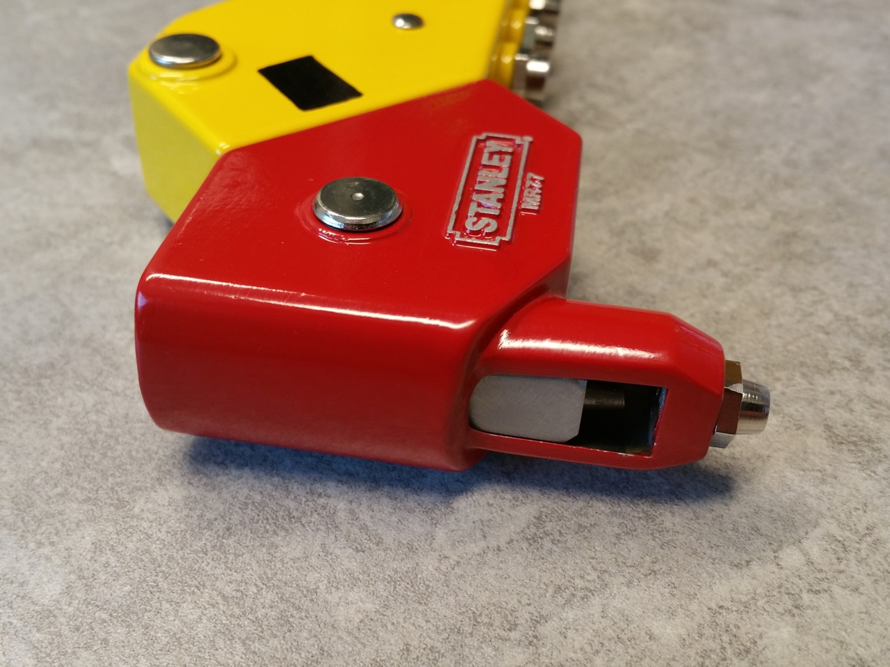
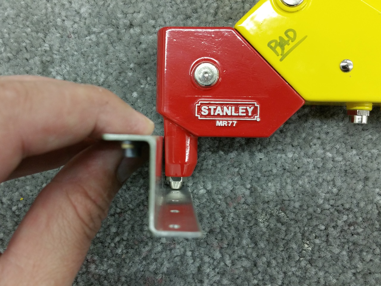
So, armed with 12 oz of sealant (two 6 oz cartridges), Semco gun, MEK, and lots of gloves and rags, it was time.
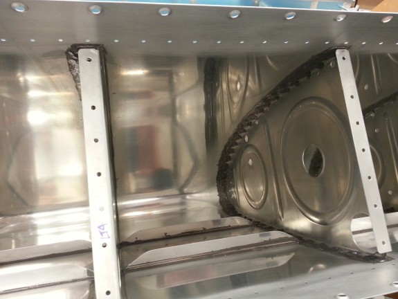
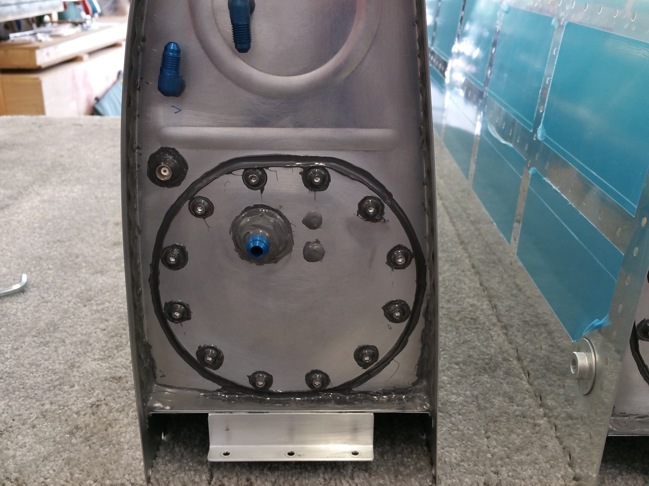
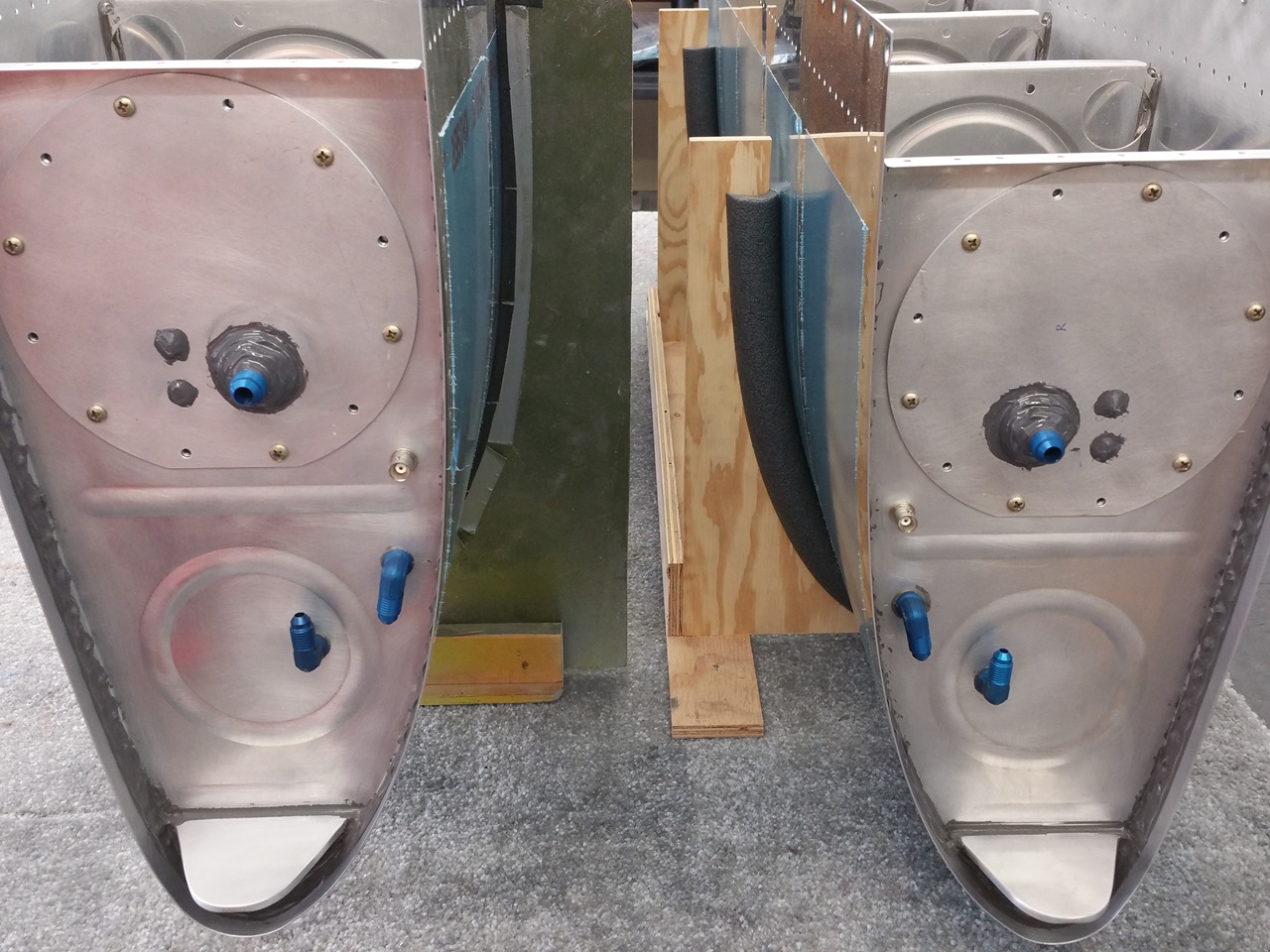
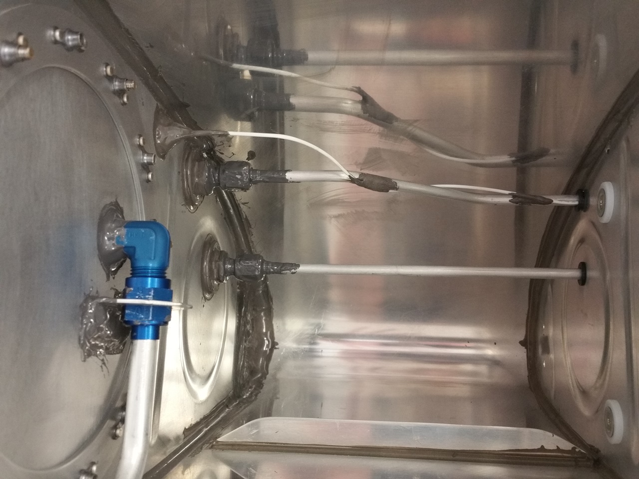
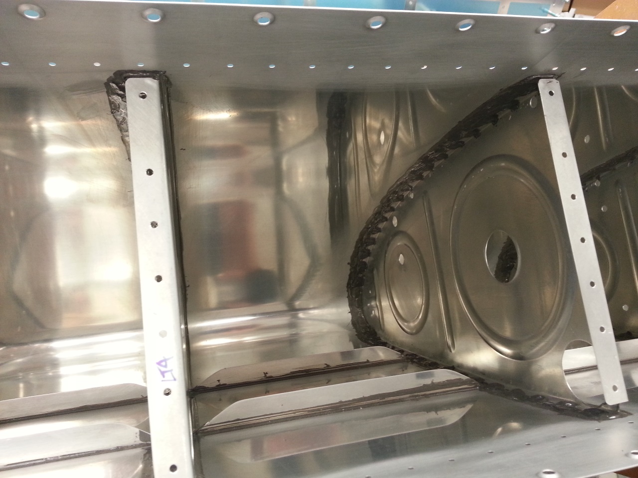
Inside the Tanks

Inside the Tanks

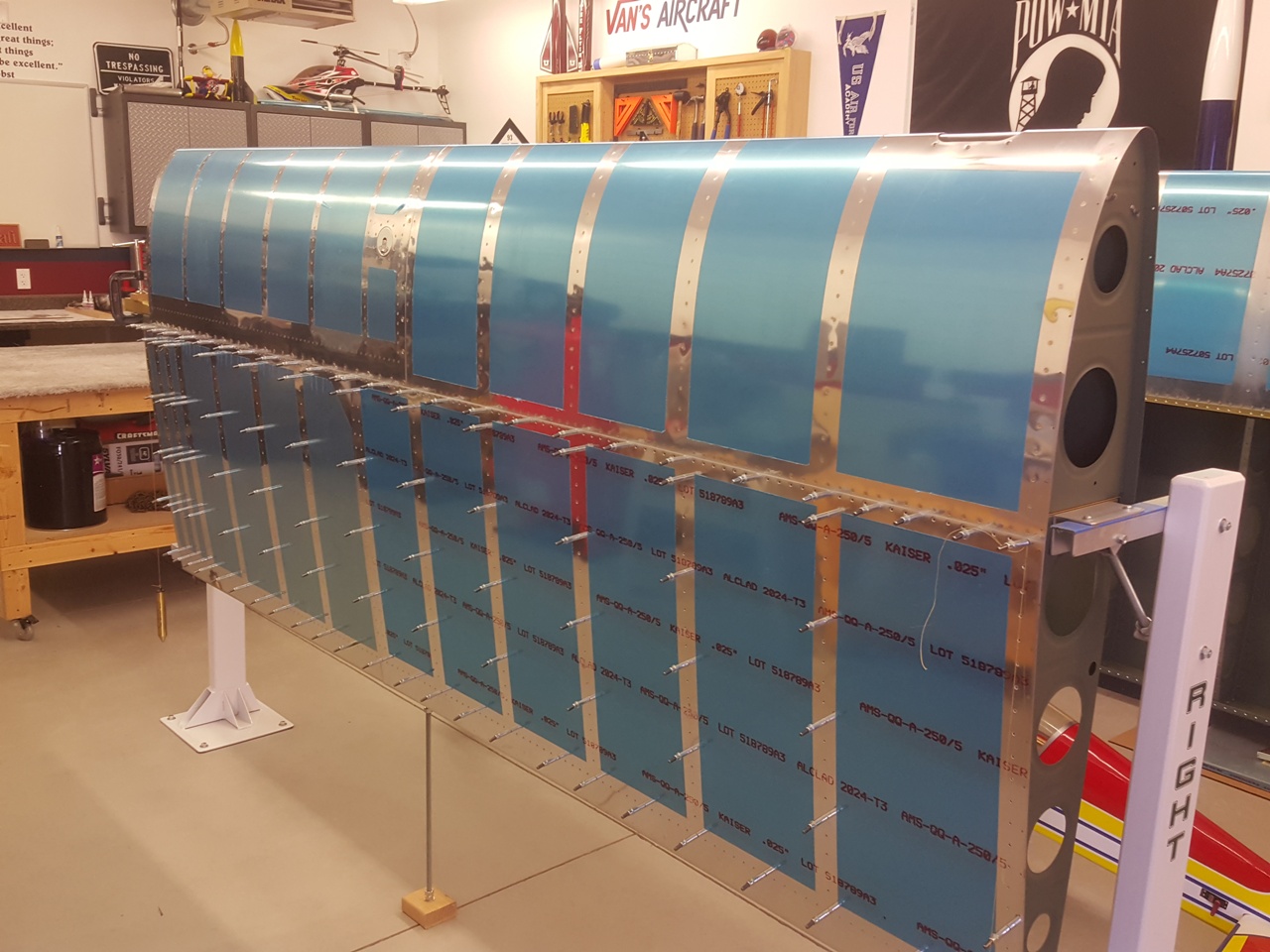
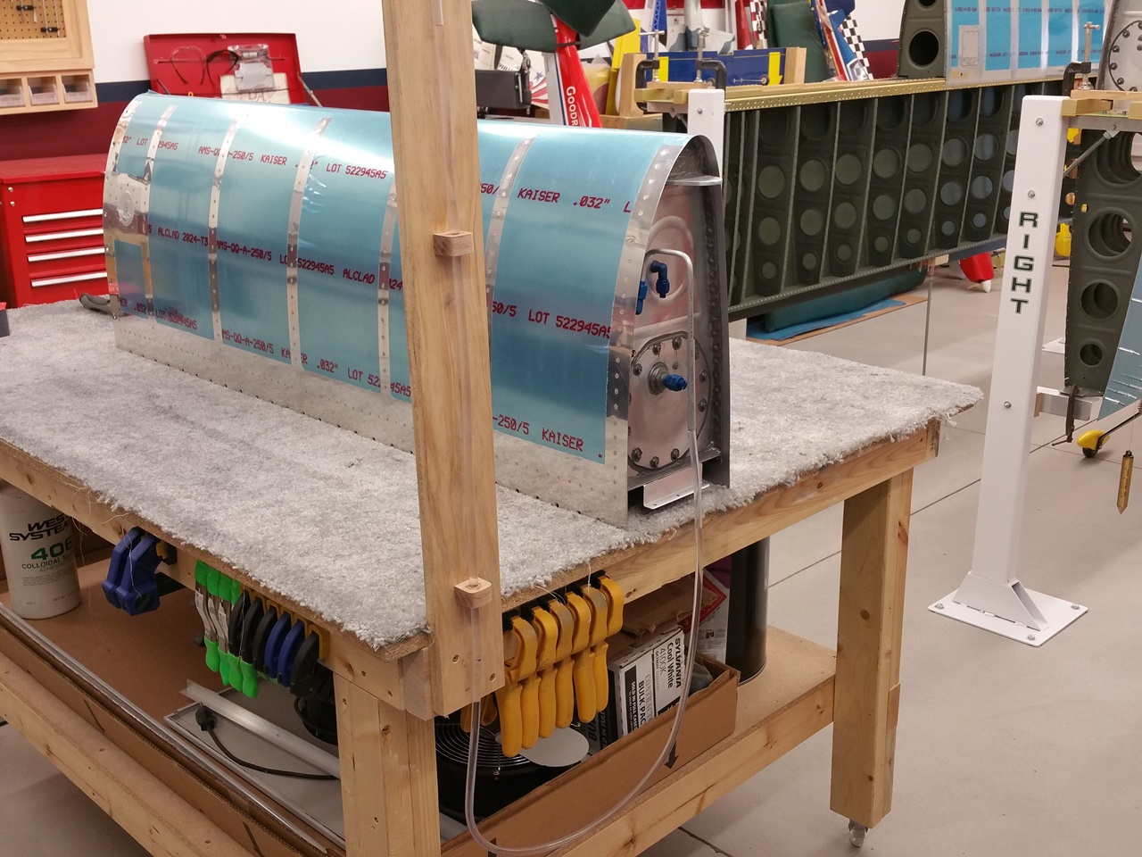
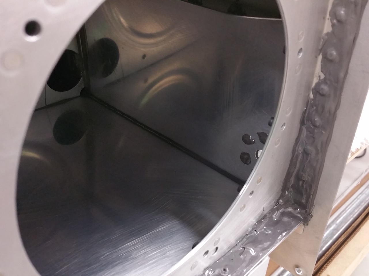
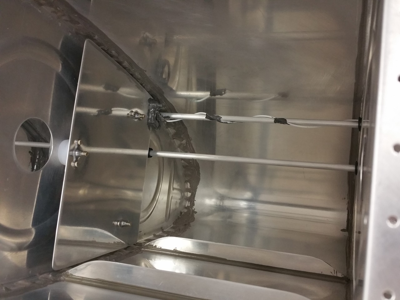
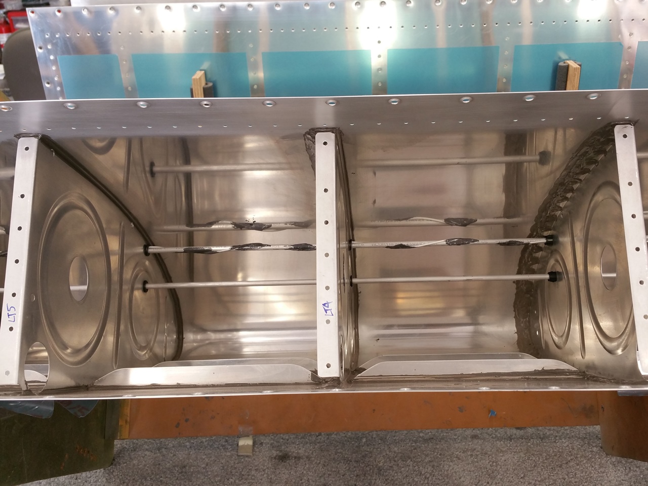
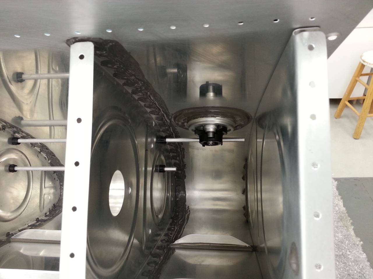
Since the ribs were sealed 8 months ago to the skins, the risk of them pulling apart from the skins was, well, zero. Some airplanes actually seal ribs to skins and call it good, no rivets. I removed all the clecos from the bottom side of the right tank. I figured it has been a long time since I riveted using a gun and bucking bar, so starting on the bottom was a good idea in case I messed some up. Next up, I wiped all the rivet lines inside and out with a rag and MEK to clean any residual cured ProSeal in the dimples and human bi-products. I then mixed up the first cartridge of sealant and got set to rivet. Using the Semco gun, I was able to simply use the nozzle to shoot a small amount of ProSeal into each dimple. I then inserted a MEK soaked and dried rivet into each dimpled hole, and then pushed them with a sucker stick to seat them nicely in the bed of sealant in the dimple. At this point I riveted each rib, nose to end, working from the middle rib out. After each line was set, I cleaned both sides with a light wipe of MEK. This was simply to insure that the shop heads were set correct and not to leave a significant mess.

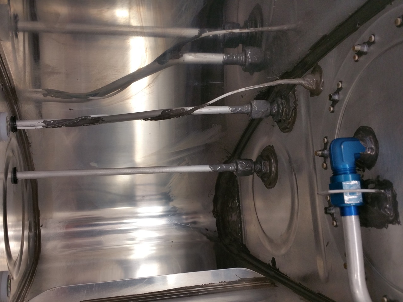
I was able to get one tank per cartridge worth of rivets done AND then hit the shop heads with a little drop of sealant, smeared with a sealant spoon, to create a completely airtight assembly. I only used about 3 oz of sealant on each tank, but did not want to risk the exceeding working time of the ProSeal. Inevitably, I needed to hit a few rivets a bit more, some I had to drill out and replace. For the most part, I did OK. All in all, I kept the ProSeal on the tanks, or on gloves and rags. Pretty clean surprisingly.
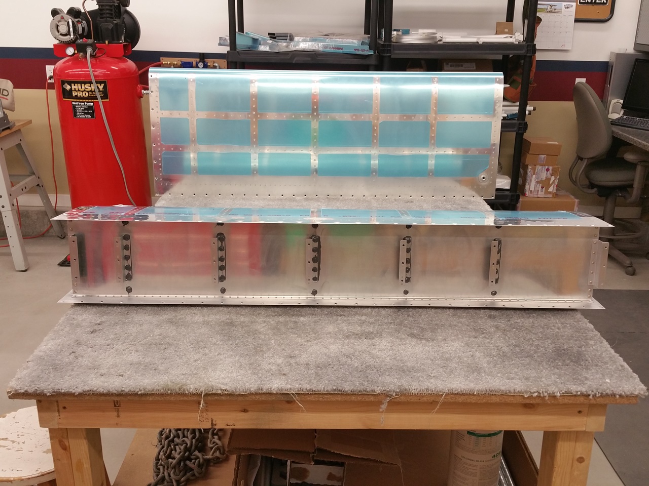
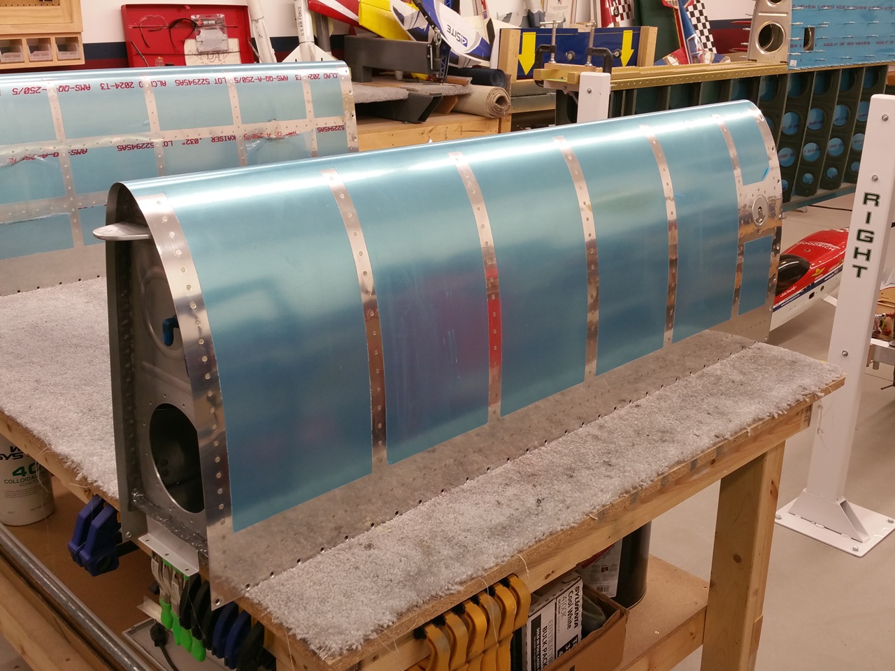
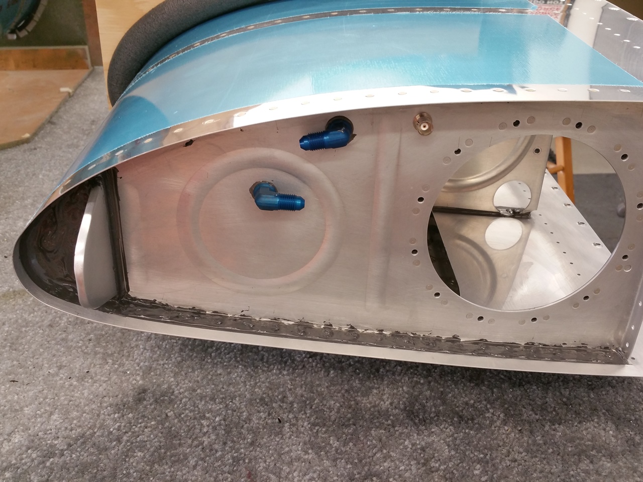
Cleaned and Set

Set and Cleaned Up

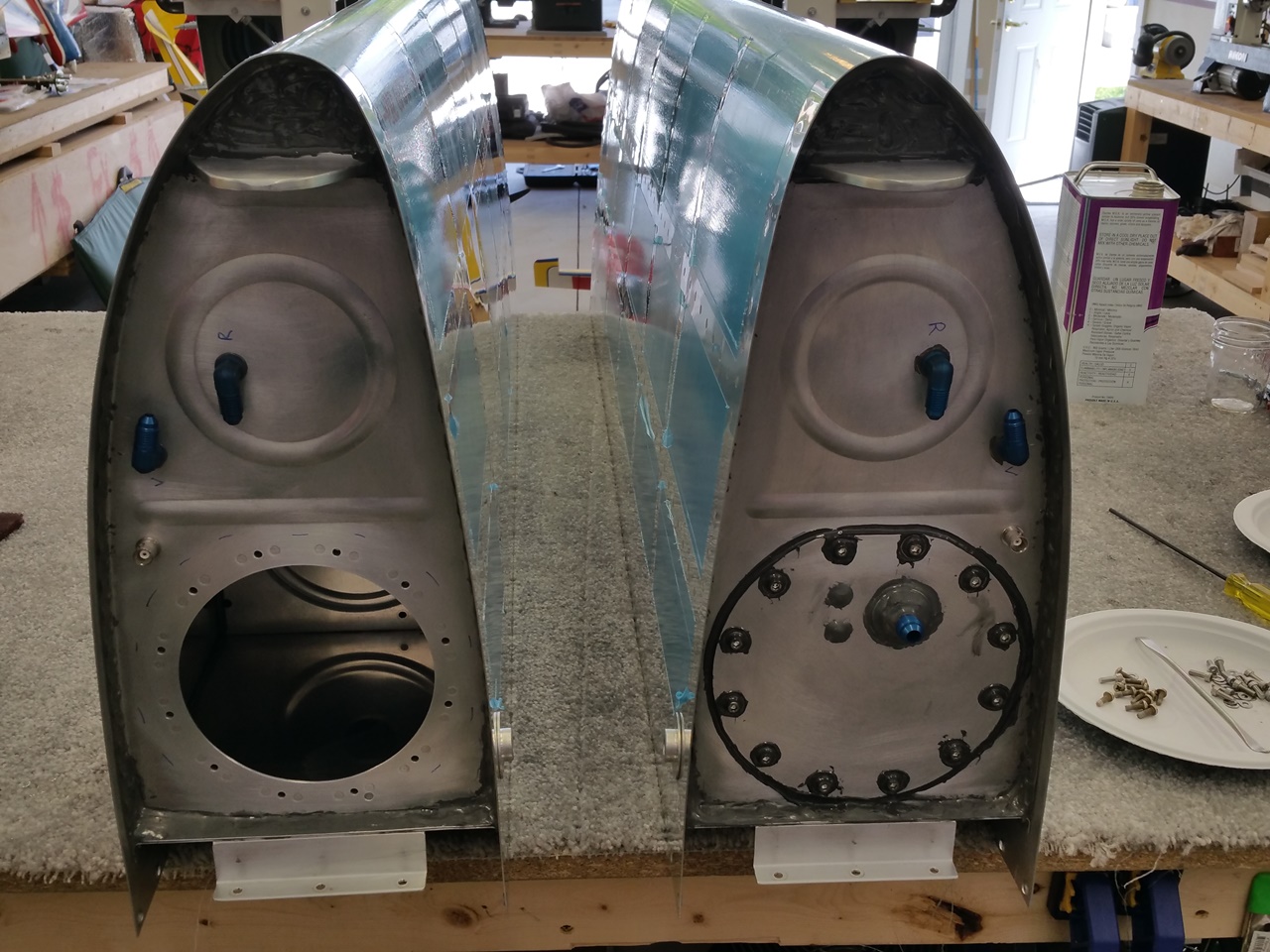
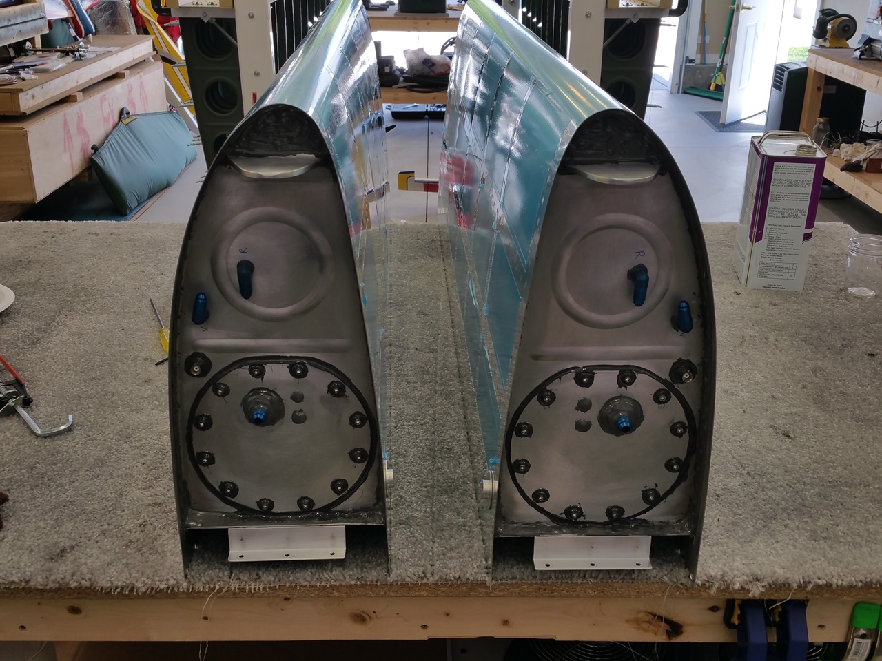
I spent nearly until 1600 riveting, cleaning, checking, sealing, etc. Needless to say, I am sore in places I have not been sore in some time…again. Some of my manufactured heads are sitting a little high, but I know a little cheat…rivet shaving, that will clean those up. That will of course happen after all the sealant is cured and likely before paint. For the most part, they turned out pretty good. I think this may have been in part the sealant that ended up on the flush rivet set not permitting a good hit. It could have been technique being a little rusty. It could have been too much sealant under the countersink. When I say high…we’re talking very slight.

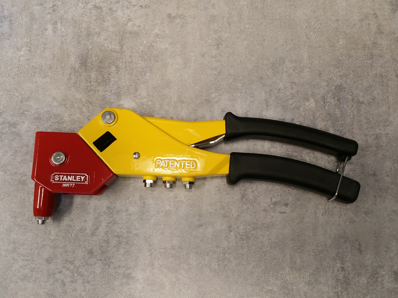
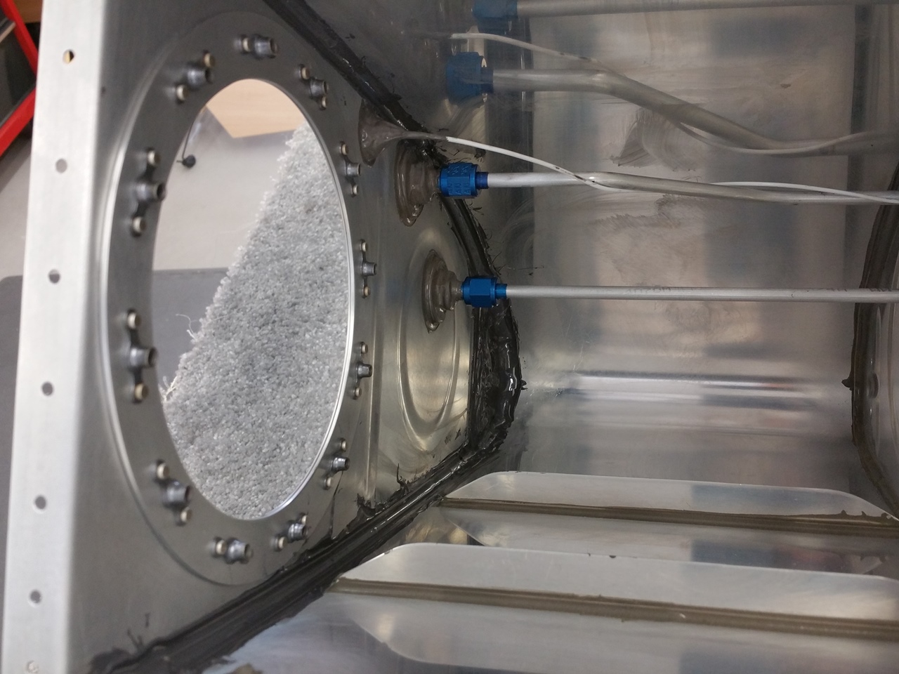
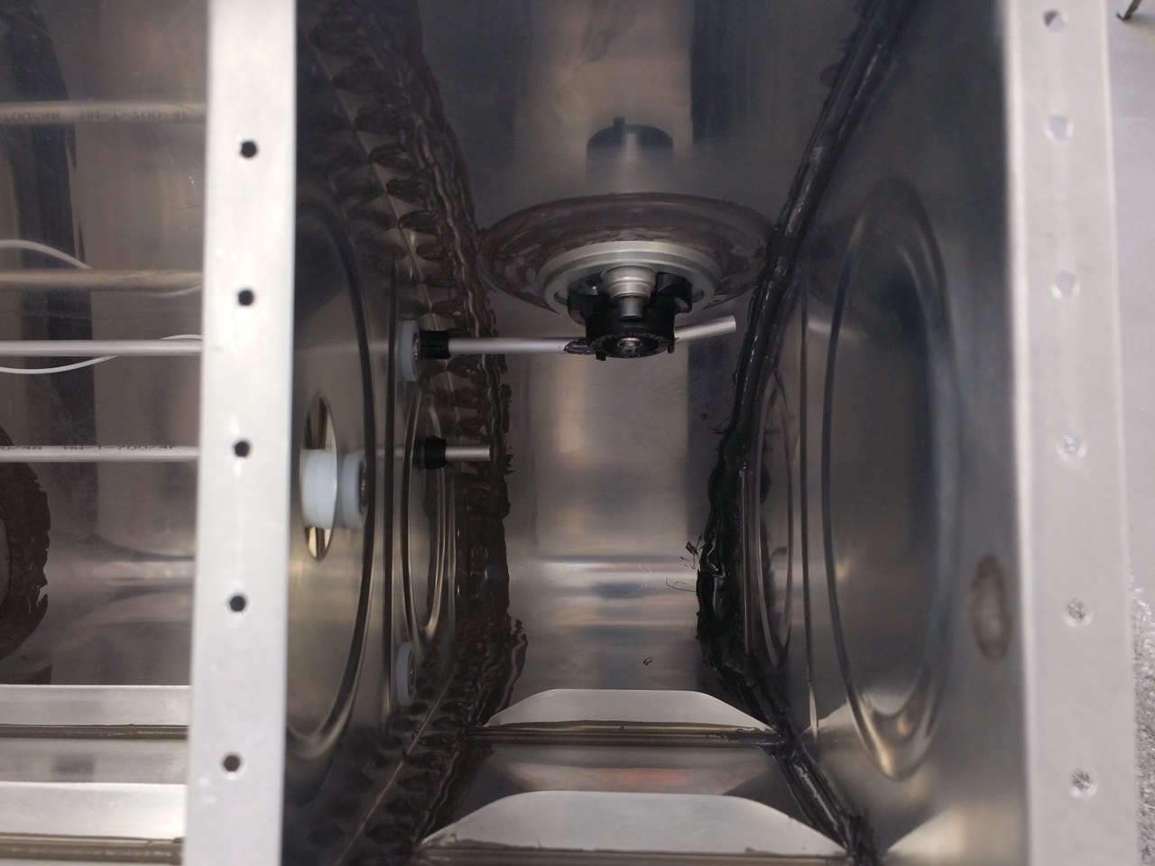
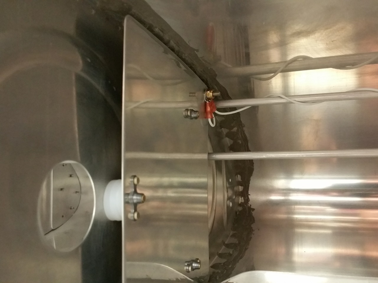
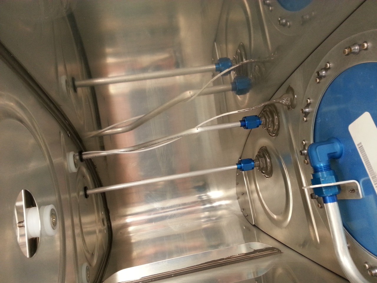
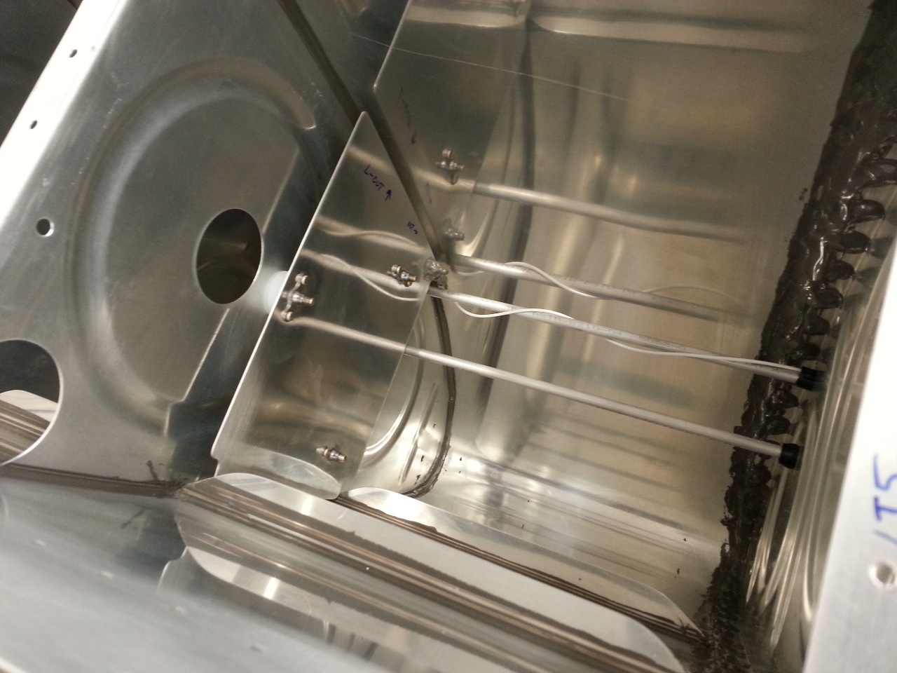
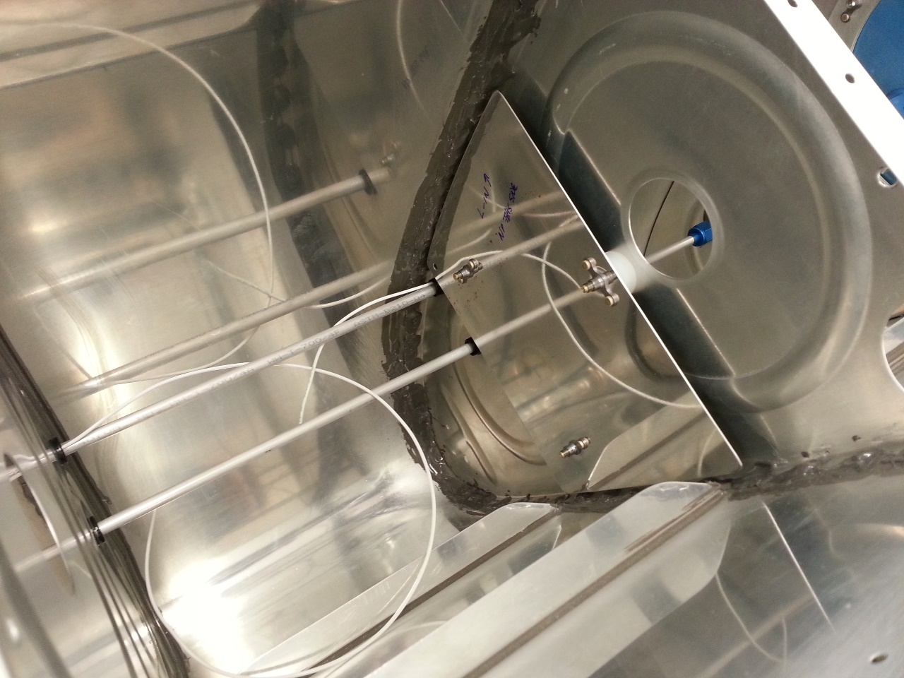
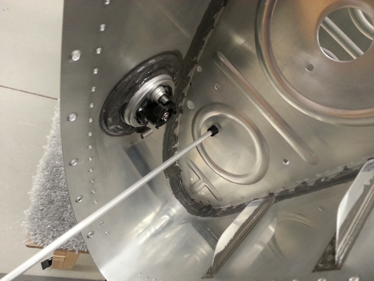
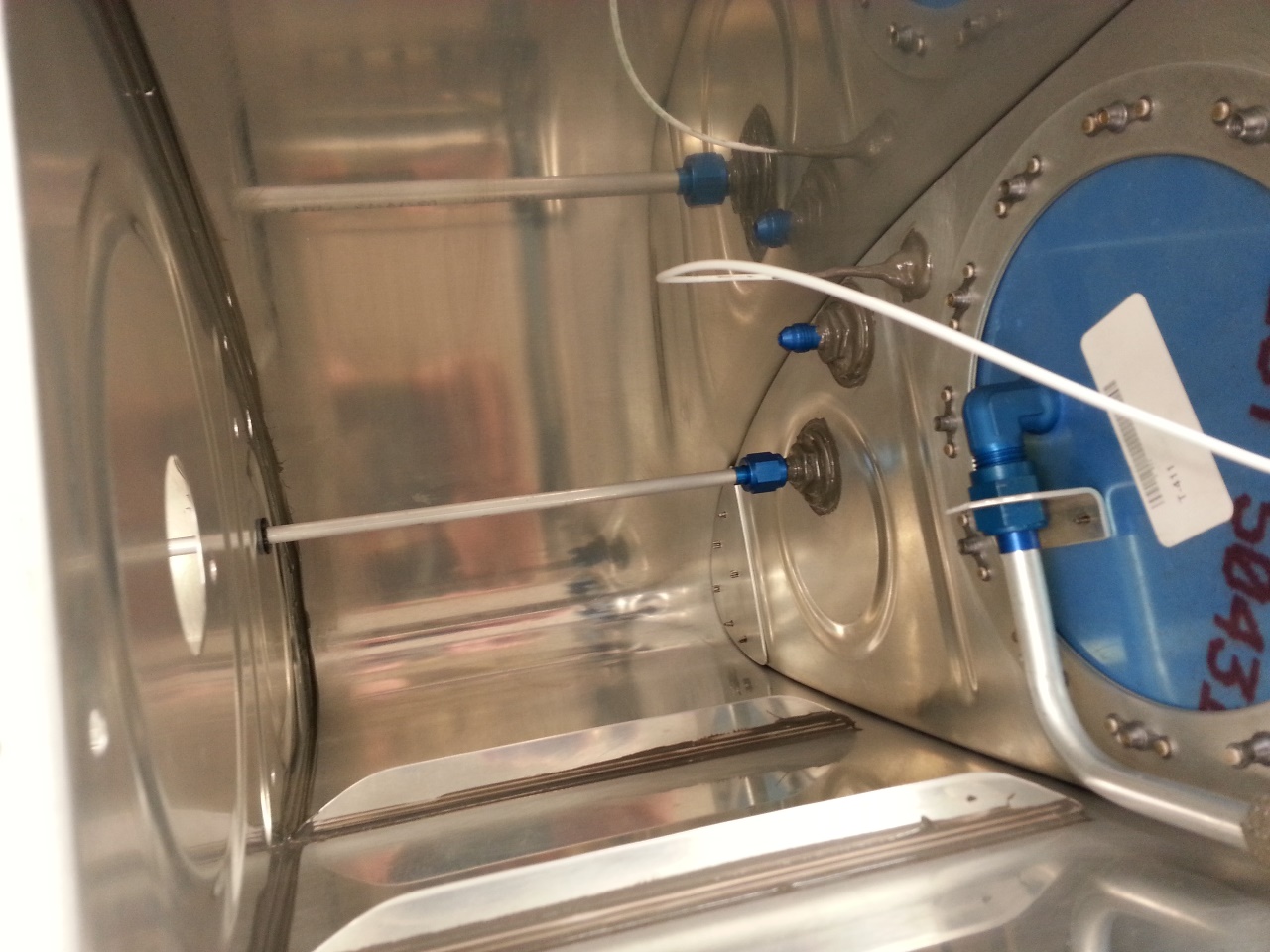
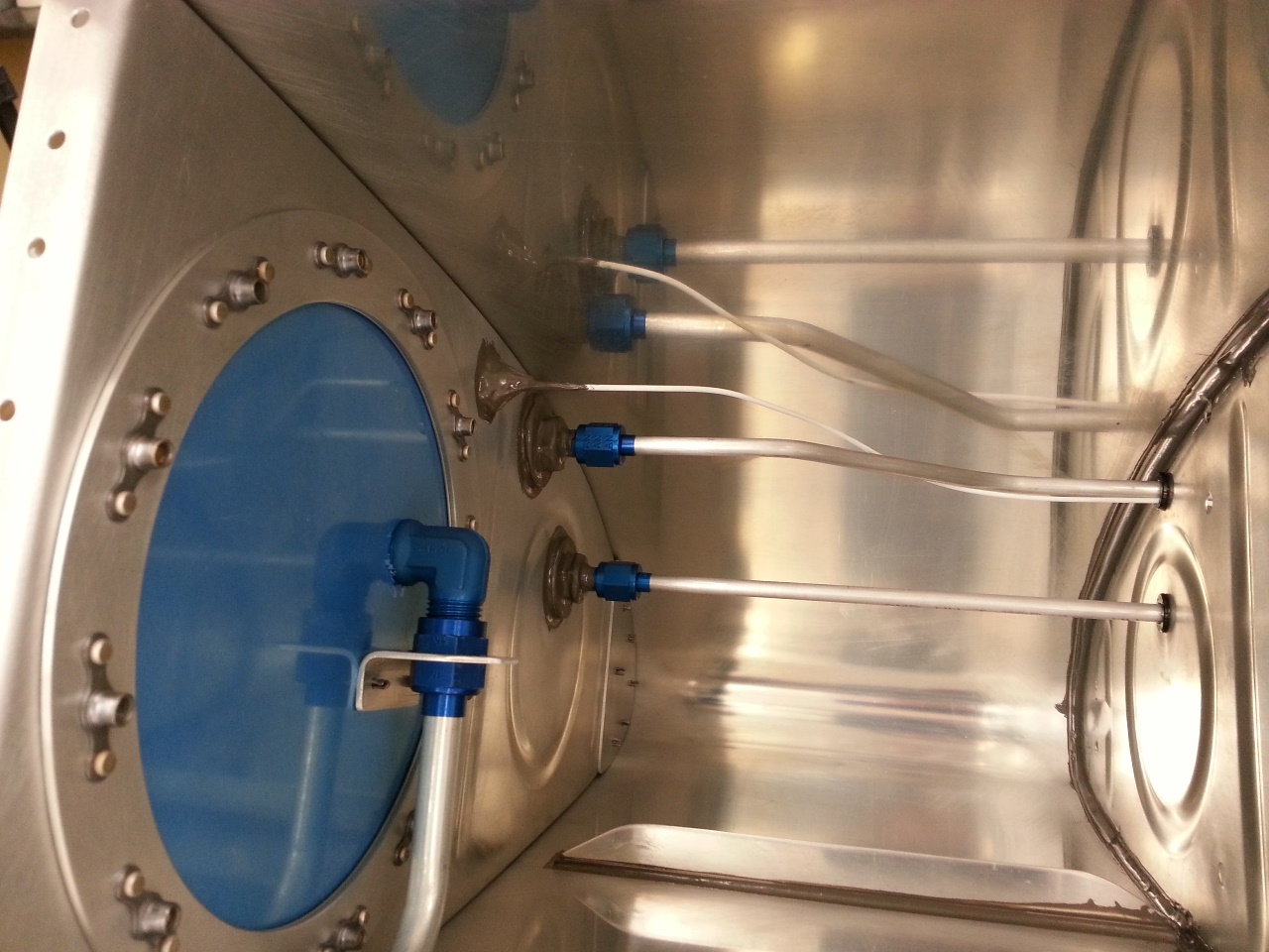
I think I will take Monday off and let this sealant cure for a week in the house before moving on. I will need it to recover from the body soreness anyway. 🙂 Next up will be the plumbing of vent/return lines, capacitive fuel sender wiring/plate install, and then riveting/sealing of the inboard and outboard ribs. Fortunately the rest of the riveting on the tanks is done with a squeezer or rivet puller. As for now, the gun/bucking bar method is done on the tanks. I really cannot wait to be done with ProSeal.


Categories: Tanks

Tanks resume some more…

May 17th, 2014 No comments

Sorry, no pictures again. I did however complete the work I started earlier this week.

Basically, I cleaned all the holes of extra proseal in preparation for wet setting the rivets.

Took a bunch of time, but it was work. Work that needed to be done.

Now I simply need to wipe each rivet line clean with MEK and go to town riveting.

Categories: Tanks