Archive

Archive for November, 2011

Riblet Complete

November 23rd, 2011 No comments

Match Drilled and Ready for Dimples

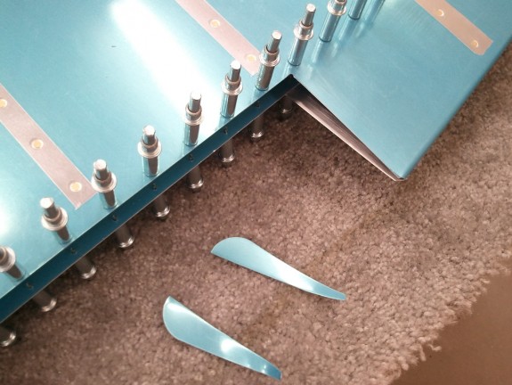
Since today is the day before Thanksgiving, I had some “non RV” tasks on the list, I decided to get at least one thing done. That one thing would be match drilling the riblet to the skin.

The part I stewed over is how many holes and where they should be located. The riblet is just long enough to me that it warranted 3 rivets on each side and one on the small tabs. Others have used only 2 per side, but I kinda felt that it left the ends of the flanges with too much length from the rivet to the edge. I seems that the size is right in the middle of going with 3 or 2 rivets. I ultimately decided that 3 was it for me. I spaced them at 1 1/8th” from each other. This caught both ends of the flanges and tucked in the center. I think it will look just fine.

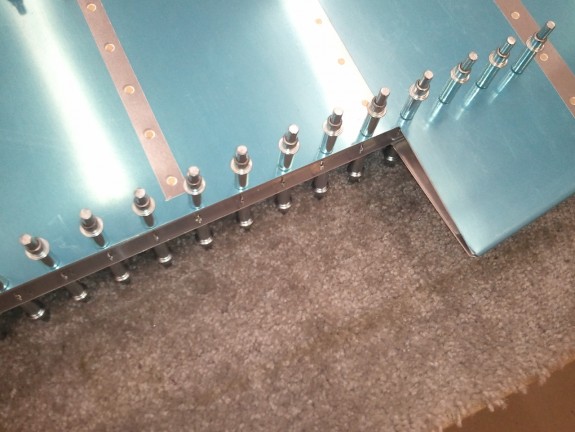
All clecod in, the riblet is nice and straight from the trim spar to the trailing edge bend. It is ready for dimpling with the rest of the parts and the skin and then on to elevator assembly.

Categories: Elevators

Elevator Riblet Fabricated

November 21st, 2011 No comments

1 Down, 2 Remain

Giving credit to Jason Beaver again, I liked his riblet design on his work. I emailed him and asked for his process. It was simple enough. Basically, you make a paper template of the riblet until you are satisfied with the fit. Then you copy that to some 0.032″ scrap and cut it out and then bend it with a pair of hand seamers. Sounded easy enough. The thing I liked about Jason’s design is that it tied the trim spar in the elevator to the riblet rather than simply closing off the end like other builders have done. The thought is that it will reduce/eliminate more twisting at the corner of the skin and the spar and hopefully keep cracks from forming in the corner of the elevator skin where stresses are focused. Since the original design was simply to fold over some ears, this may be overkill, but heck…why not?

After some careful measurements, I generated a template pattern on my computer and printed it on a file folder. I have the vector file now if other builders want a head start. I then cut it out and then scored the bend lines and what do you know, it fit nicely. I figured I was on the right track. With some minor tweaking, I updated my file on my computer, reprinted, cut out, bent, and fitted. I had a winner.

I then transferred the pattern to some sheet scrap and cut it out on my band saw. I then cleaned it up on my disk sander and dressed up the edges. Now it was time to bend. I placed the sheet stock in the jaws of my hand seamer and started to it. That is where all heck fell apart.

One of the challenges of bending metal is knowing where to bend to get the part to be the right size post bend. Paper and metal are totally different beasts. The other issue was the little flanges to capture the spar. Bending these takes a little finesse over the large flanges. As I was bending the first little flange, it cracked right at the bend line. There goes that attempt. I actually cut off the smaller flanges and web and figured it could work as a riblet just fine. Turns out, it fit quite nicely.

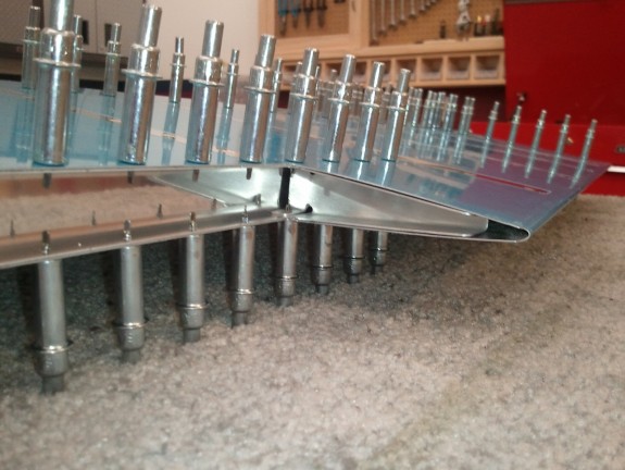
I still wanted to make one that captured the spar. So I repeated the process on try #2. I slowed down some and took my time on the smaller flanges this time. It paid off, however, the web of this riblet was too wide and the rib did not fit very well.
Riblet After Much Tweaking

They say that the third time is a charm. It turned out to be true here. I was able to get another cut, bent just right with no cracking, and fitting nicely. Mine is not as tight to the trim spar as Jason Beaver’s rib, but it fits and works and it really stiffens up this area. I match drilled the smaller flanges to the spar/skin. Next up is match drilling it to the trailing edge.
Straight and Clean

It was time to call it a night. Here you can see the rib in and ready to be drilled to the skin. All in all, it turned out OK. Bending may have been easier to try, but at this point, I like the clean look the riblet creates and the added rigidity it also adds. Time will tell if the extra work to get it to tie into the trim spar was worth it. Thanks for the idea and tips Jason B!

Categories: Elevators

Elevator Trim Tab Cutout Ears

November 19th, 2011 No comments

Prepping for Riblet

One of the more interesting parts of the Left Elevator is the area where the trim tab is attached. On the inboard edge of the elevator skins (and on the tab itself), Vans leaves little ears that need to be folded over to close off the end of the skin. MANY builders have completely mangled the skins trying to accomplish a clean bend and have to settle for a not so nice look to this step. I read several other build logs, researched on VansAirforce, and gave the steps a healthy think through.

The same “many” builders that experienced bad bends and did not want to live with the ugly result have sometimes simply cut the bad bends off and fabricated a little biblet to replace the ears. Some other builders have opted to just do the riblet as a first attempt without risking the initial heartache of the bad bend. One example of a builder that opted to simply do the riblet from the start is Jason Beaver. I review his site every so often as I go along (as with others) and I liked his solution. I opted to do the same. So, today, I committed to it and lopped off the elevator skin ears.

I used my appropriate offset shears and cut about a 16th short of the line desired, which is essentially a line perpendicular to the trim tab spar, on the top and bottom of the skin. I then filed little by little to a point where the skin corner/edge would have been if I had bent it. This left a nice straight and clean cut line. At this point…I was mentally spent for the day. I hope I made the right choice. If not though…I can always buy parts to do it over. 😉


Categories: Elevators

Trim Servo Done

November 1st, 2011 No comments

It Clears...Just

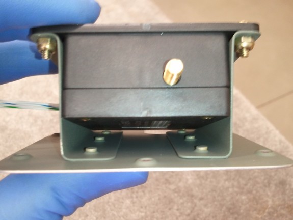
I decided to install the servo Z brackets with NAS1097 rivets in the last 2 aft holes. This allowed me to countersink the holes rather than dimple and still get good clearance of the servo when installed. It is tight, but clears. 0.032″ skins are just enough for AD3’s. I was careful to not over countersink but it was close.

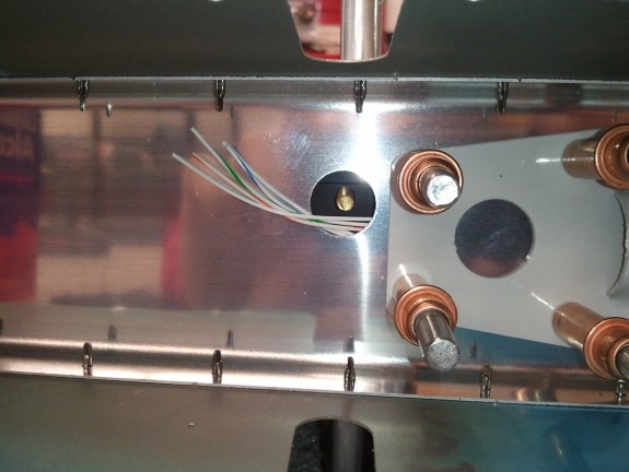
Right where it Should Be

As mentioned in the prior log entry, the location of the servo per the plans is not right. As you can see here, I located it where it does belong and the jack shaft of the servo lines right up where it belongs. I do not like that they want you to have the wires exit in the same hole so I may open up a 3/8″ hole just above (below in this picture) the jack shaft hole, to route the wires for the servo through to avoid any interference.

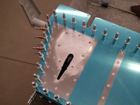
Fits as it Should

Trim cover plate installed. You can see the arm of the servo is right in the middle of the slot and ready for the tab. Looks good to me. Now I have to take it out and start match drilling the skins to the skeleton and prep for the trim tab assembly. The other item I need to think about is how to hookup and where to route the trim servo wiring. I have a few ideas…we’ll see how it ends up down the road.

Categories: Elevators