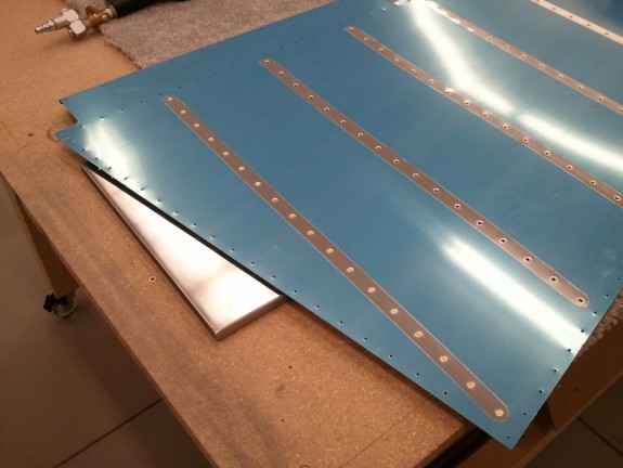
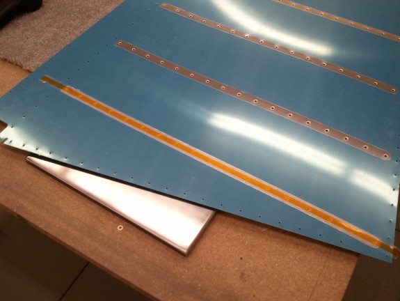
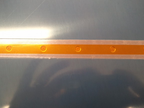
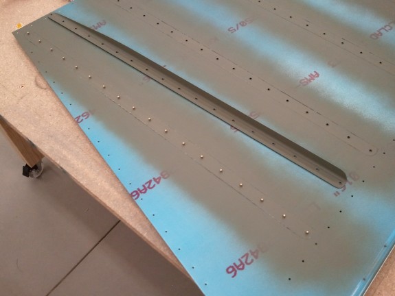
Stiffeners Done, On to the Substructure!
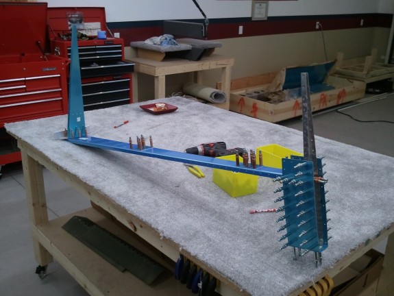
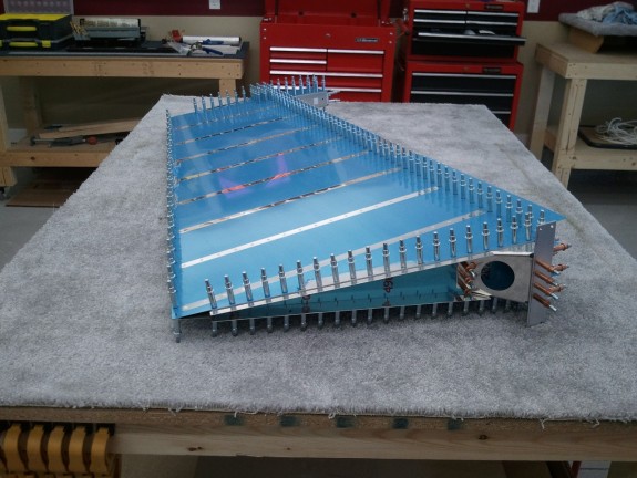
With the stiffeners now complete and riveted onto the skin, it was time to move onto the skeleton of the rudder. Here you see the spar, ribs, re-enforcement plates, counter balance, and rudder horn clecoed together. This was after the top and counterbalance ribs were fluted straight. The structure is then match drilled to #30 and the counterbalance skin is match drilled to #40. Again…the precision of the pre-punched kits really shines through. It simply lines right up.
Here you can see one of the important parts of the plane. It is the rudder control horn. Cables will attach to the outboard ends and then run up to the rudder pedals in the cockpit. The 3/8ths holes is for one of the ball joints that will make up a pivot point of the rudder. It took a little love and filing and Scotchbrite wheeling to get it to nestle in with the rib above, but it turned out a great fit. One of the parts that Van’s has you fabricate is a shim that fits under this horn so that you can tie the horn, spar, and the rib together all fitting at the same level. It was pretty easy to make out of 0.032″ sheet stock.
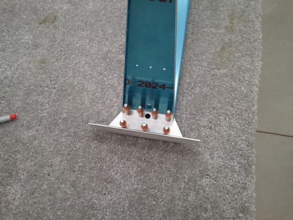
Here you see the rudder nearly completely assembled and clecoed together. The substructure is complete, the Rudder horn reinforcement is in and drilled, and at this stage I am fabricating the other two parts Van’s makes you create. These little strips of sheet stock will be what holds the lower fiberglass fairing onto the rudder. A few simple cuts and you match drill to the rest of the already assembled parts.
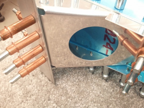
One of the more challenging parts of assembling the rudder is this reinforcement part. First, you have to cut some sizable ears off of it using the standard practice of trimming to the center of the guide holes Van’s pre-drills in the part. Some have found that it is difficult to do this and still retain good edge distance for the holes. Either I am lucky, or Van’s has improved the part because I trimmed to the center and then installed and match drilled and it came out with some room to spare. Here you can see that I have good edge distance and the part clears the web of the adjoining rib. Whew. I have also heard that they used to make you bend this part to the shape they now ship it as. Man am I glad…cause that would have been a bear.
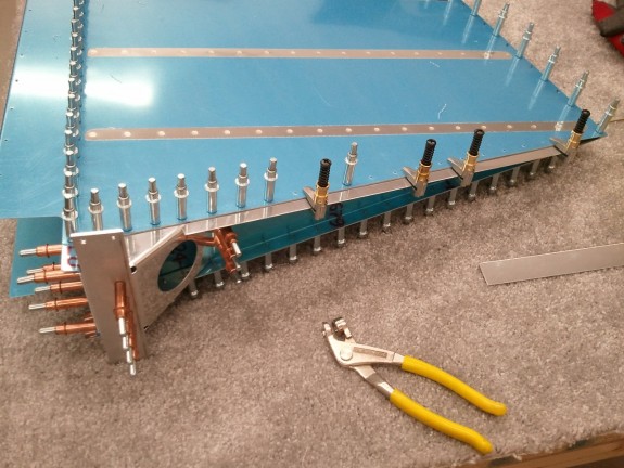
After all the fabrication of parts and assembly it was time for all the remaining match drilling. I was able to get it done in short order. The one thing to remember on the rudder is that the trailing edge is NOT drilled perpendicular to the skin but IS drilled perpendicular to the cord. Careful attention however helps and avoids to much trouble as the AEX wedge is pre-drilled to the right angle and helps align the bit as you are match drilling the parts. Still remember not to fight the flow of the bit.
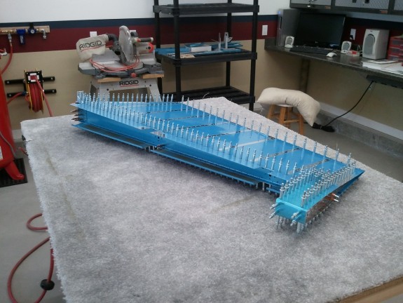
Here is another view of the rudder match drilled and ready to…take all apart again. Just when you think you got something, you have to tear it down and do a TON more work. It is fun to show the kids though…”look at the size of this!!!” I love it when my kids reply, “WOW, that is soooo cool!” Motivation for sure.
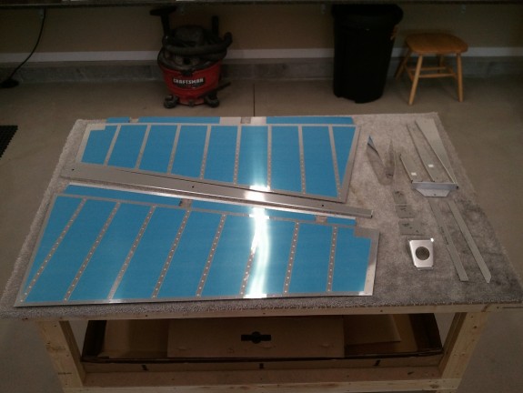
It got late in the evening by the time I was done match drilling the rudder. So I tore it all down and got everything ready to finish all the prep before paint and turned out the lights. Here is where the Rudder stood once it was all said and done. All in all…a great build session. Thanks for the shop pass Dear!

