Full Day of Horizontal Stabilizer Work
After a good restful sleep, it was time to get some real work done. I mentioned in the previous post, several mistakes have been made in the assembly of the HS by other builders. I did not want to make the same ones and was now willing to take a swing at it.
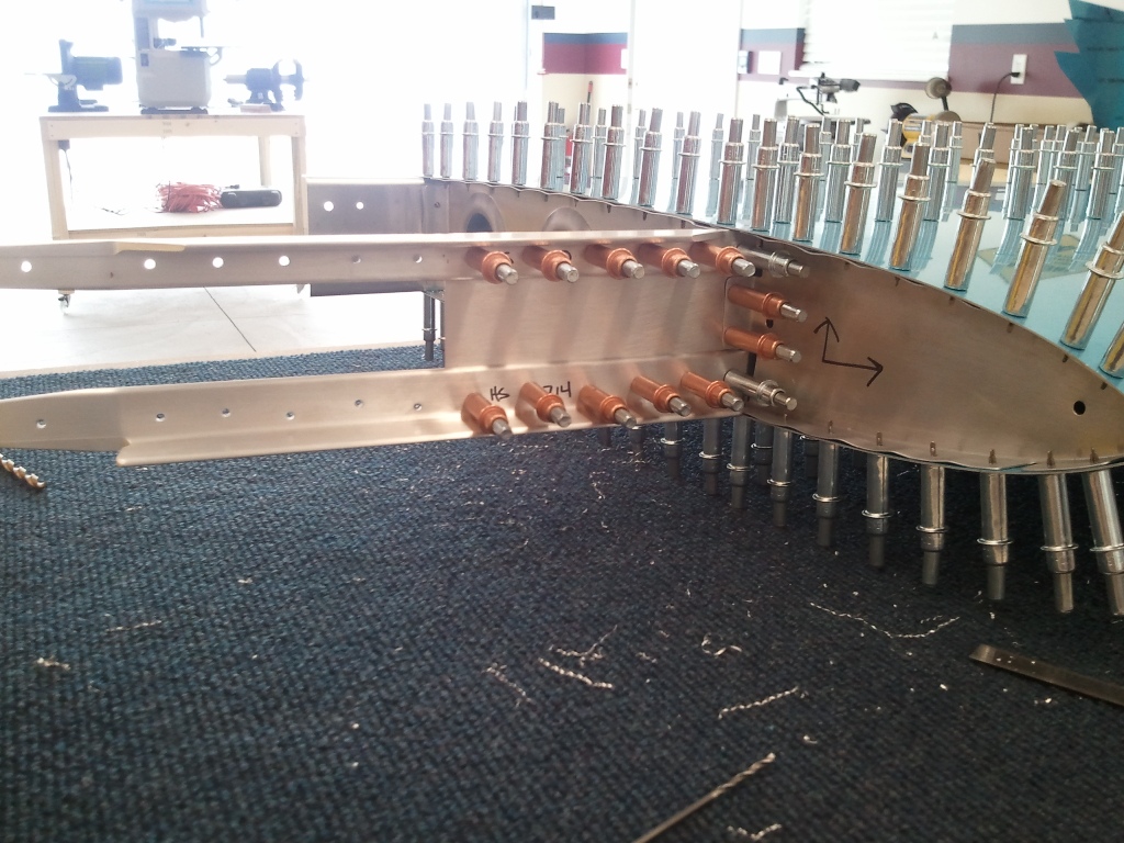
The first area of concern is the flange of the forward HS404 Rib to the HS702 spar connection. Despite my best efforts, I made a similar mistake that others have. The problem stems from needing to drill from the back side of the HS405 rib, through the HS702 spar into, the HS404 flange. You are essentially doing this blind. This left me with the 2 holes in the flange a little closer to the 2x Diameter to the center of the #30 hole distance recommended, but within the MilSpec (MS) required edge distance. The other contributing factor is that when the HS404 rib is installed into the skin opening for it, it causes the rib to concave some and moves the flange inward. The flange could be scabbed and replaced, but I have chosen to build on as it is not a structural connection and it is within the MilSpec.
The second problem with the backside drilling is that some have busted the edge distance of the stiffeners when drilling though the spar and the stiffeners. I was very concerned about this connection as it IS structural for the empennage. I was VERY careful here and pleased to report that on the left side, I was well within the edge distance when drilling these holes. Whew!!!
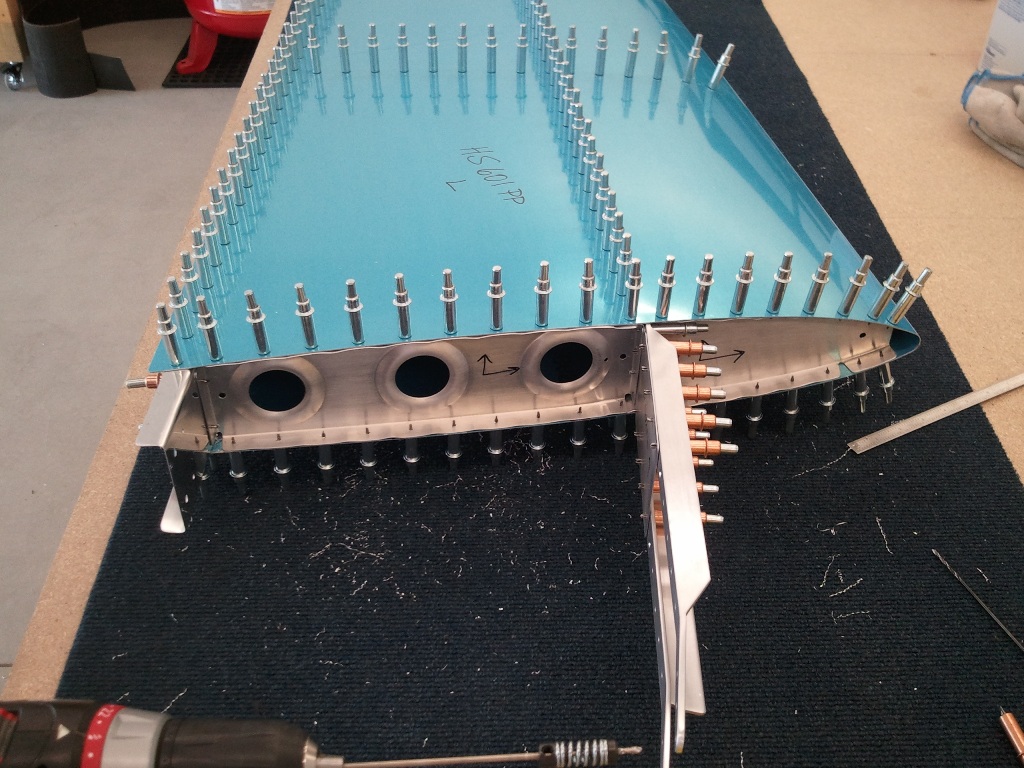
Once the HS404 and HS405 ribs are match drilled to the skin, you then completely match drill ALL the holes in the skin to the sub structure. My hand got sore undoing and redoing all those clecos. Remember, they are on both sides of the HS in this picture. I love how precise all the punched holes are in all the parts Vans supplies. Made lining up everything a real dream. In older kits, you had to lay out the rivet holes in the skin and then drill them all then match drill them to the sub structure. I am glad I don’t.
The above shot is of the Left HS complete and ready to be disassembled. Wait…I jut got it all together and looking cool. What do you mean I have to take apart. Welcome to building a plane. I took out all those clecos, and set the parts aside. Then next step is to dimple all the holes and the corresponding holes in the sub structure to accept the flush AD3 rivets. Then I will prime and begin to reassemble for the final time. The real riveting will begin soon enough.
With the left side complete, it is time to repeat all the steps just completed for the right side. With the hard stuff figured out, and experience now fresh…this will go like a breeze right? WRONG!
Remember back in the HS405′s Prepped and Drilled post when I noted that forward flanges were not located symmetrically? Well it came back to bite me. I was able to successfully drill the HS404 to HS702 flange connection correct this time, but when it came to the stiffeners….well, I thought, heck it worked on the other side just right…it will work here fine too. Long story short, when drilling through the HS405 through HS702 through HS710 hole, I looked and was horrified to see that the hole looked to have busted the 2x Diameter edge distance. After a few thumps to my head in frustration, I measured the hole. I am at 0.250″ from the center of the hole to the edge! That 1/4″ looks way smaller when you are scared. Crisis averted.
New Builders beware of the HS405 webs….they are not created equal and must be the cause of this common mistake. The forward flange IS NOT CENTERED on the rib. You will get different height holes on the HS710 and HS714’s no matter what you do!
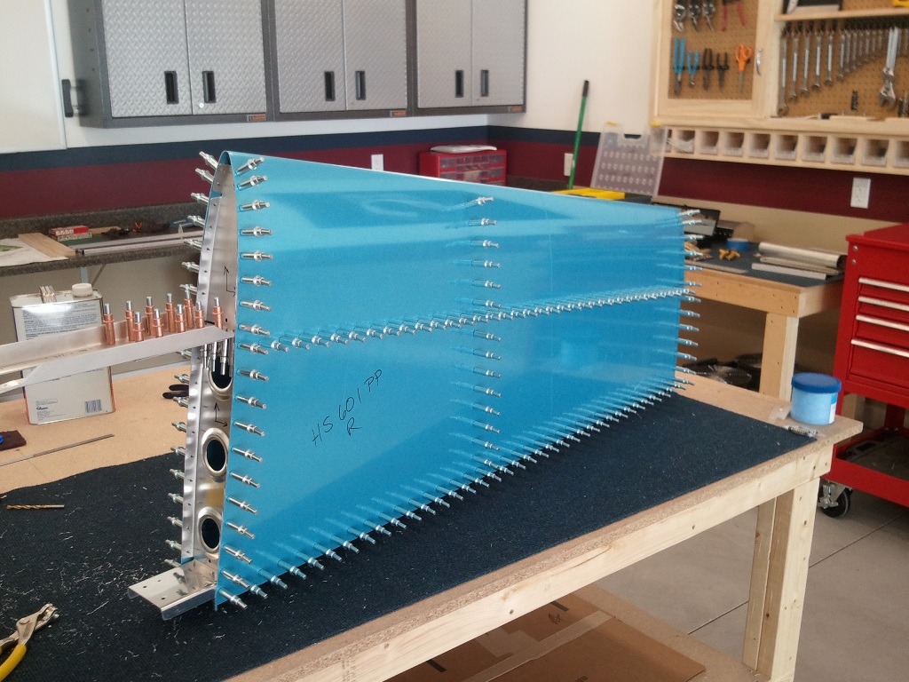
Once I recovered from what I thought would be a costly mistake, I pressed on and match drilled the right HS Skin to the skeleton. If I had enough clecos, I could have made a full HS looking structure temporarily. Alas…in time, I will do it permanently.
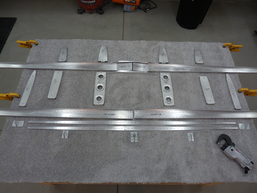
The last thing to get accomplished today was to clean all the skeleton parts, lightly scuff them, and then mark the part numbers and locations on them. I will dimple the parts sometime this week and then clean once more and then prime them. Additionally, I will use my DRDT-2 to dimple the skins and then prime the inside of them. Then the fun of riveting will begin. THAT was a good day of real progress.

