New E-606PP Arrives

February 15th, 2012 No comments

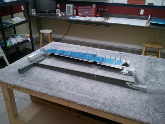
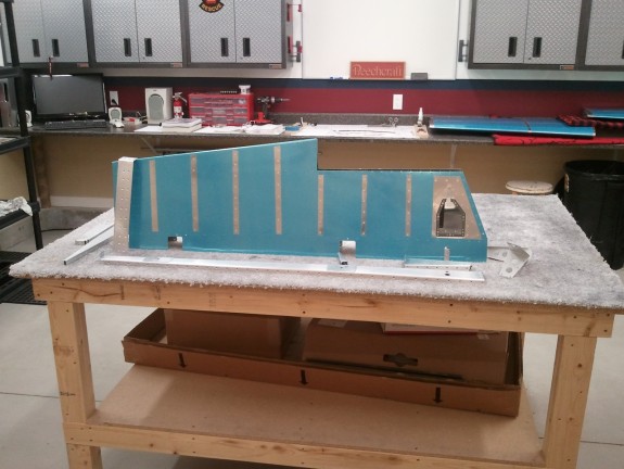
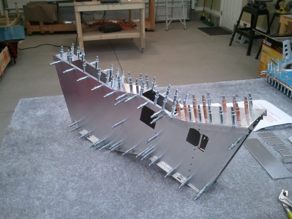
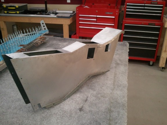
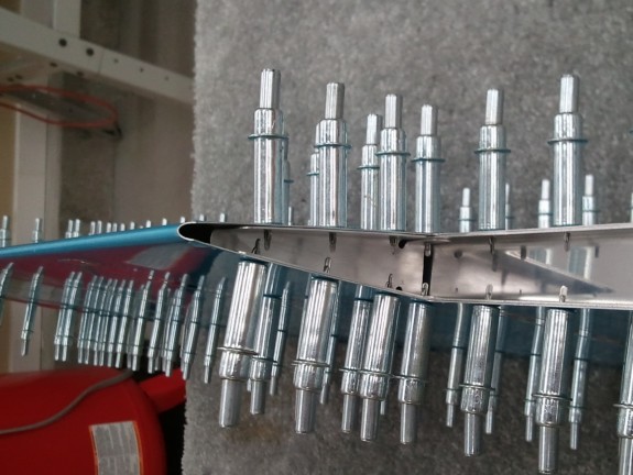
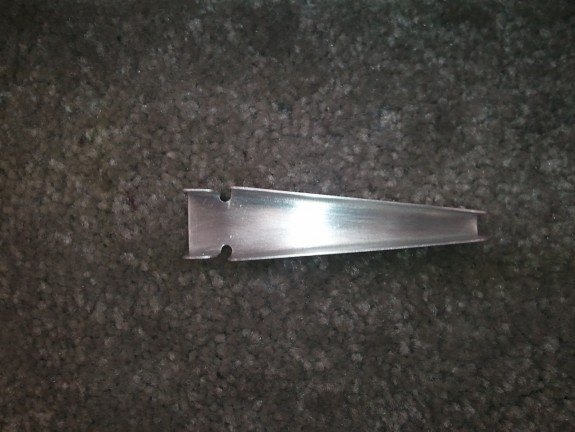
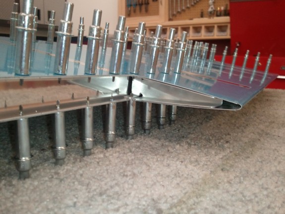
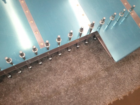
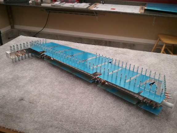
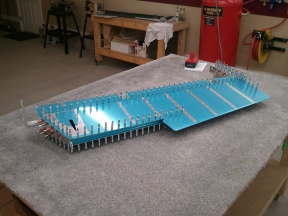
No pictures tonight. The new E-606PP trim spar arrived and I ran it out to the shop. I slid it into position, matched drilled it, and countersunk the upper holes. This time I used the same matched drilled backer and the countersunk holes looked great. I then dimpled the spar, the skin and slid in the assembled skeleton previously done, and clecoed it all together for fun.

Hopefully this weekend I can prime the skin and spar and be able to get the elevator riveted together final. Then I can move on to the trim tab itself.

Categories: Elevators

Inspired by…

February 13th, 2012 No comments

Inspiration

Each year, my family attempts to give hand made gifts at Christmas to the siblings on a rotating schedule. We do not always succeed, but we try.

This last year my sister Amy had me on the rotation. Since she was aware that I had just built a shop to build a plane in, she commissioned a neighbor of mine that cuts vinyl to cut the motto of our Grandfather.

The idea was that I could put it somewhere on my shop walls for inspiration and encouragement.

I finally was able to get it stuck on the wall. It is now a central focus of the shop.

Thanks AMIS!


Categories: Hangar Chat

One Step Closer

February 11th, 2012 No comments

As far as the parts could go

Saturday came and it was a nice day to boot. I got some honey do’s done and then headed to the shop. Since prepping all the parts aside from the trim spar for primer, I knocked out spraying them. While the primer was drying, I took the time to remove the blue vinyl from the rivet lines on the skin, deburr it, and dimple all the holes except where the trim spar goes to be able to match drill it when it arrives.

I then scuffed the skin for primer but the temp fell to far to shoot it. So I looked at the assembly instructions for the skeleton and determined I could start riveting the parts together without causing any trouble to getting the new E-606PP spar taken care of.

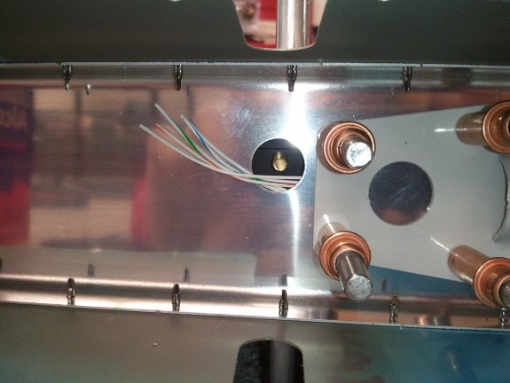
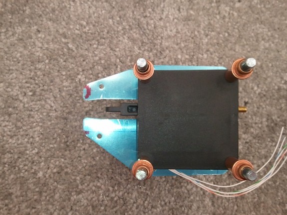
The above shot is at the end of the building session. I was able to get the skeleton mostly complete. I love how it all lines up. You can also see my wire exit hole near the hole for the trim servo jack screw.

Everything went straight forward as it could have. I love having the right tools for the job. If you have not purchased a longeron yoke for your squeezer…do it now! As for now, I am as far as the parts can take me on the elevator.

Categories: Elevators

Left Elevator Work Resumes

February 9th, 2012 No comments

Dimpled and Scuffed, Ready for Primer

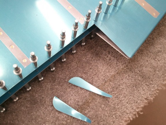
I decided now that I have heat, I needed to get back to work on the plane. It has been a few months and life has been busy. Since the last build session concluded with the match drilling being mostly complete, and I keep a good list of where I am in the manual, starting up again was a breeze. I got back to work prepping the rear trim spar (E-606PP) for the trim tab. I needed to disassemble the spar from the skin and countersink the upper holes where the hinge for the trim tab will go.

I set up my countersink cage with my piloted countersink to get these done. Here is where I made a small error. Since the spar is .032″ thick material, and the holes have to be a little deeper to accept the dimple of the skin, I forgot that it may open the hole a little more which will allow the pilot to no longer center and cause chattering. That is what happened on the first hole. Once the hole was opened up larger than the pilot, it made a real mess of the hole. The pilot was able to wander all over.

Some may say that the larger hole is a real problem. Traditionally yes it would if the spar being countersunk and the skin were the only parts being riveted together here. However, eventually the trim tab hinge will be added underneath, and this spar will be sandwiched between the hinge and the skin. There will be plenty of support for the shop head and the parts will lock together just fine.

So how do you keep the pilot from wandering? I grabbed a piece of scrap sheet stock and simply matched drilled it to the spar and clecoed it to the spar so that as I cut the material out of the spar hole, it still had a good hole for the pilot to continue to hold the cutter solid. This worked great for the rest of the holes that had to be countersunk.

Once the holes on the top were done, I dimpled the rest. As for the first chattered hole, I decided I would finish the rest of the hole prep and then decide what to do with this one. As I was dimpling the underside of the spar, I missed a hole with my dimple set in my pneumatic squeezer and punched a hole bigger. At this point, I decided it was time for a new rear spar.  As cheap as the parts are for the tail, it was an easy decision.

The rest of the night, I deburred, dimpled, and prepped the rest of the skeleton parts for primer. I did not dimple the skin tonight but will in the next build session.

I also added a 3/8″ hole in the E-702 spar just below the hole for the jack screw for the trim screw. I did not like the idea of the trim servo wire sharing the same hole with a piece of threaded rod. I centered the hole between the existing hole and the flange of the spar. It sits exactly centered with the existing hole as well. I think this will be a better way of routing the wire. I got the idea from another builder and have been told that no strength will be lost with a hole of this size here. Both holes will get snap bushings down the road.

It was now time to close up shop for the night and order the new trim spar.

Categories: Elevators

Fun with Blimps

February 8th, 2012 No comments

Glamor Shot

One of the things I love to do is give back to my community. If it can involve flying, all the better. While the particulars of the above are not public, the photo is. That is me sitting left seat as we were permitted to do a promo photo shoot for CAP. Needless to say, we are assisting the U.S. Army to help keep you safer at home. I love to fly and this is a neat project to be a part of.

Categories: Hangar Chat

Needed Upgrade Complete

February 7th, 2012 No comments

Heater Mounted to UniStrut

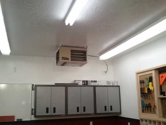
When I built the shop, I always intended to heat it some how. I insulated it really well, installed an insulated man and garage door, wired an outlet up in a corner, and wired a thermostat wire in the wall that went to the middle of the shop. I had a good idea of what type of heater I was eventually going to run and have been watching the local suppliers for good deals and something that would work. Since the shop was completed in April of 2011, there was no real pressing need to get a heater in at that point so I just put it on the back burner. 🙂

As winter began to approach this year, I began to think heavily about it again. When the temperature started dropping, so did my motivation to be in the shop working. As you can see, my build progress has been much slower since. The Holidays did not help either. I called a local RV’er that also does HVAC and we chatted about options, ideas, and costs. He gave me really good information, but shortly after, my money ran out as December 25th got closer.

As December 25th passed, we were blessed with some generous gifts from my parents and Grandmother. Combine that with a nice gal at Lowe’s giving me a good one time discount, I was able to get a 45000 BTU shop heater for a really decent deal. I also got the conversion kit to make it run on Propane for REALLY cheap as they were closing the kit out. I also bought the flue kit made by the manufacturer. All in all, I was out the door for no more than $400.00.

The 45000 BTU is rated to heat a 700 sq/ft garage. My shop is 720 sq/ft but really well insulated. I figured, it would be great fit as most garages are not insulated that well.

The heater is set up with mounting brackets that will natively mount to a 24″ on center truss situation. Here was challenge #1. I wanted the heat to be blown into the major area of the shop, not against a wall 16 feet away. I was sitting in my desk at work, contemplating how I could rotate the heater 90 degrees and still make it look good. Above me are cable racks suspended from threaded rods that hold pieces of UniStrut which the cable trays set on top. Solution found. I will get some UniStrut and mount it across the shop trusses and then hang the heater from them. Worked great. I painted the UniStrut so it would look good against the ceiling.
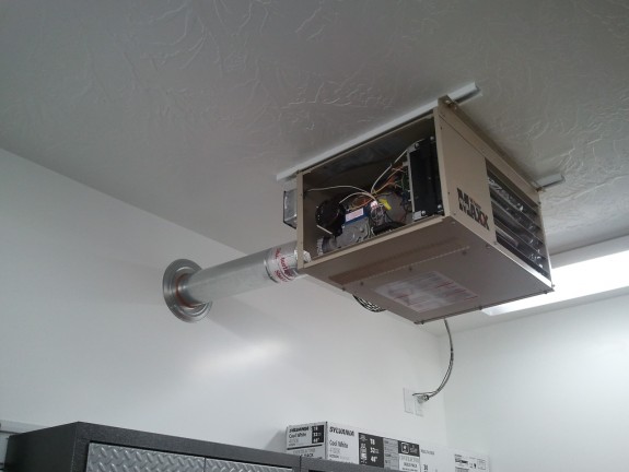
Double Wall Vent Done

I ran the wiring and installed a switch. Probably not required, but not a big deal in case it needs to be worked on. I can also just unplug it from the wall.

Next up was the vent flue. You can vent these in 2 ways. On is a traditional vertical flue and the other is a horizontal. I thought long and hard about both. I have a low pitch roof (4/12) and I filled the attic with R60 worth of insulation. It would have made a real mess and some real work to get to the spot where this vent would penetrate the ceiling and the roof. The horizontal required at 7″ hole to be cut in my fairly new wall and exterior. As you can see I chose to do the horizontal.

I began to use the flue kit that the manufacture designed for the heater and quickly realized I paid too much for too many parts for a simple run through the wall. So I boxed it up and returned it. I then ran to a local HVAC parts supplier and bought only what I needed. Saved nearly half over the manufacturer kit and got only what I needed. If you are going through the roof, the kit is nice and you will use most of the parts, but horizontally, it is not worth it.
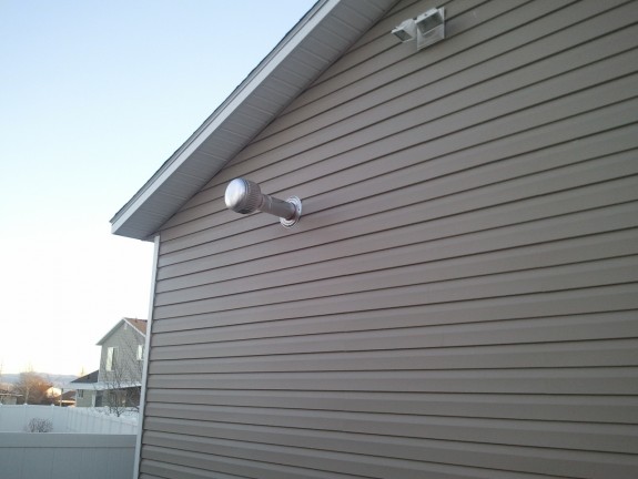
The Exterior of the Vent Flue

Here is the view from the outside of the shop. The vent is required to be at least 12″ beyond the exterior. This is 12.25″ and looks just fine. It must also be 4 feet from any vented soffit. Since my eve is not vented here, not an issue. This is on the back of the shop…so I will never see it. My Dad suggested I put a smiley face on the cap for my neighbors to dress it up. 🙂 Nah.
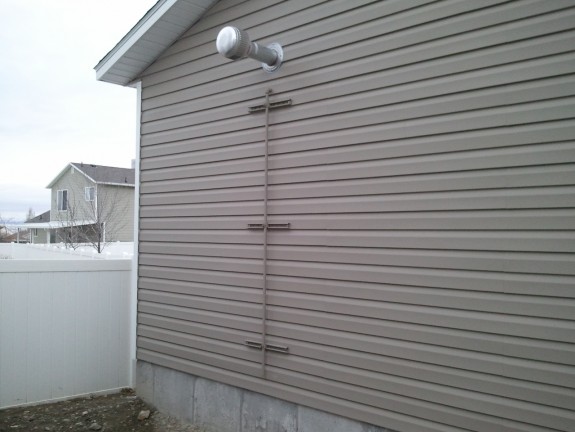
Gas Line Anchored to Shop Wall

Next up was installing the hard line from near the foundation, through the wall, and to the heater. I simply used more of the same UniStrut I hung the heater from inside. Since my exterior is vinyl siding, and lagging the UniStrut right to the wall would squish it, I had my machinist friend make me some 1″ dia 5/8″ thick standoffs. This way the siding still floats around the standoffs, but the UniStrut is SOLID to the wall. I then drilled a 7/8″ hole in the wall for the 1/2″ black pipe to penetrate through. I then used the standard clips to hold the pipe to the UniStrut. Needless to say, you can hang off this pipe. I also found an off the shelf can of paint that matched the color of the siding and painted all the exterior parts for both corrosion resistance and so it would blend in to the building better. I think it looks great. Again, all this is on the back of the shop. Out of site out of mind.

At this point I can either run a Natural Gas line to this drop or I can drop a large Propane tank. This pipe will work for either and meets code.
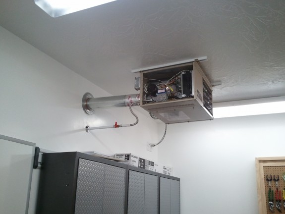
Gas Line Plumbed

Next was the interior hookup. I asked about a dirt leg in the line and was told that they are not required here. This was especially true given the rise in the line to the heater. I can always add one later, but none of the appliances in my house have them and they have been good for many years. I painted the interior portion of the pipe white to blend in. I also put a cheap trim ring near the wall. Overkill to some, but a cheap way to dress it up a bit.

Now was the time to decide which gas. To get Natural gas to the shop is a BIG deal (and would have during original construction as well). I have to trench 18″ deep about 100 feet from the other side of the house without chopping through my sprinkler, telephone lines, pay to have the line installed/inspected, all while the ground is frozen solid. Not sounding like a fun winter prospect. I did buy the Propane conversion kit. I can have a local LP company lease me a 125 gallon tank for $48.00 a year and then I pay for the fuel at a reduced bulk price and no delivery fee on a schedule. The local HVAC/RV’r did a cost compare and that did not help me decide one way or another as some have convenience over $$ perks that come out nearly at a wash.

I have decided in the short term to convert the heater to LP and get the tank. As the winter thaws, I may then decide on the NG line and work and then convert it back to NG. If the consumption of the LP is low enough, I may simply keep the big tank and then have a backup in the event of a NG shortage. 😉
Heat, Glorious Heat!

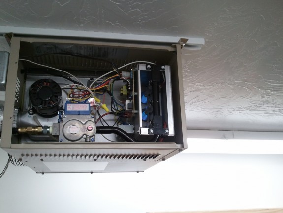
I converted the control valve to LP. Changed the pressure spring and the burner orifices, and then hooked up a standard 20 lb Propane cylinder to test it and set the proper manifold pressure. With a flip of a switch on the thermostat, I had glorious blue flames. Within 10 minutes of running it, I had increased the shop 10 degrees! This thing is surprisingly quiet. I had to turn it off after a bit because I was tempted to run the whole cylinder. I think this will be a VERY nice addition to the shop. The bonus is that I can run only the fan in the summer and it will circulate the air and help with cooling.
Heater Ready to Run

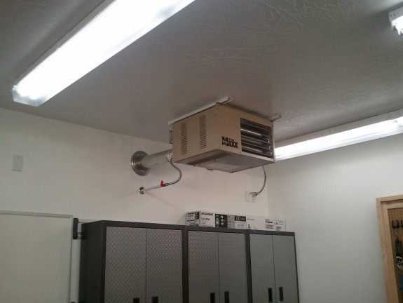
So here it is all buttoned up. I still need to schedule with the LP company and get the tank dropped and filled. I adapted the exterior pipe to run off a smaller cylinder until then. It looks a little silly to have a small tank attached to the shop…but, it will do in a pinch until the big tank arrives.

Again, as it warms up, I can always trench, get a NG line installed, and convert it back to NG. But for now…I am loving this little heater. Now, it is time to get back to building the plane.

Categories: RV Factory/Shop

Center Console Built…uh…

January 26th, 2012 No comments

Center Console Kit!

A while ago, a little note was posted on Vansairforce.net about the vendor that designed and made a kit for making a decent center console for the RV side by sides. I have always liked the idea and was a little concerned that I would perhaps miss my chance to get one of these nice looking kits.

Turns out that a quick email to the designer asking if he had some residual stock yielded a chance for me to grab one that he still had on the shelf. I know I am a long way away from the fuselage, but I did not want to miss my chance, so I ordered the kit.

What you get is a nicely laser cut kit that goes together much like any kit from Vans. I was inventorying the parts when I just got a wild hare and started throwing it together. By the end of 2 hours, I had all the bends done and was able to get what you see above done.

I actually spent the next few days knocking it out and it is now complete and set aside waiting for a fuselage to be installed in. I like the design and the ease of getting it in an out if needed. Time will tell if I end up using it, but for now…I like it.

Ready for Upholstry

Categories: Fuselage

Riblet Complete

November 23rd, 2011 No comments

Match Drilled and Ready for Dimples

Since today is the day before Thanksgiving, I had some “non RV” tasks on the list, I decided to get at least one thing done. That one thing would be match drilling the riblet to the skin.

The part I stewed over is how many holes and where they should be located. The riblet is just long enough to me that it warranted 3 rivets on each side and one on the small tabs. Others have used only 2 per side, but I kinda felt that it left the ends of the flanges with too much length from the rivet to the edge. I seems that the size is right in the middle of going with 3 or 2 rivets. I ultimately decided that 3 was it for me. I spaced them at 1 1/8th” from each other. This caught both ends of the flanges and tucked in the center. I think it will look just fine.

All clecod in, the riblet is nice and straight from the trim spar to the trailing edge bend. It is ready for dimpling with the rest of the parts and the skin and then on to elevator assembly.

Categories: Elevators

Elevator Riblet Fabricated

November 21st, 2011 No comments

1 Down, 2 Remain

Giving credit to Jason Beaver again, I liked his riblet design on his work. I emailed him and asked for his process. It was simple enough. Basically, you make a paper template of the riblet until you are satisfied with the fit. Then you copy that to some 0.032″ scrap and cut it out and then bend it with a pair of hand seamers. Sounded easy enough. The thing I liked about Jason’s design is that it tied the trim spar in the elevator to the riblet rather than simply closing off the end like other builders have done. The thought is that it will reduce/eliminate more twisting at the corner of the skin and the spar and hopefully keep cracks from forming in the corner of the elevator skin where stresses are focused. Since the original design was simply to fold over some ears, this may be overkill, but heck…why not?

After some careful measurements, I generated a template pattern on my computer and printed it on a file folder. I have the vector file now if other builders want a head start. I then cut it out and then scored the bend lines and what do you know, it fit nicely. I figured I was on the right track. With some minor tweaking, I updated my file on my computer, reprinted, cut out, bent, and fitted. I had a winner.

I then transferred the pattern to some sheet scrap and cut it out on my band saw. I then cleaned it up on my disk sander and dressed up the edges. Now it was time to bend. I placed the sheet stock in the jaws of my hand seamer and started to it. That is where all heck fell apart.

One of the challenges of bending metal is knowing where to bend to get the part to be the right size post bend. Paper and metal are totally different beasts. The other issue was the little flanges to capture the spar. Bending these takes a little finesse over the large flanges. As I was bending the first little flange, it cracked right at the bend line. There goes that attempt. I actually cut off the smaller flanges and web and figured it could work as a riblet just fine. Turns out, it fit quite nicely.

I still wanted to make one that captured the spar. So I repeated the process on try #2. I slowed down some and took my time on the smaller flanges this time. It paid off, however, the web of this riblet was too wide and the rib did not fit very well.

Riblet After Much Tweaking

They say that the third time is a charm. It turned out to be true here. I was able to get another cut, bent just right with no cracking, and fitting nicely. Mine is not as tight to the trim spar as Jason Beaver’s rib, but it fits and works and it really stiffens up this area. I match drilled the smaller flanges to the spar/skin. Next up is match drilling it to the trailing edge.

Straight and Clean

It was time to call it a night. Here you can see the rib in and ready to be drilled to the skin. All in all, it turned out OK. Bending may have been easier to try, but at this point, I like the clean look the riblet creates and the added rigidity it also adds. Time will tell if the extra work to get it to tie into the trim spar was worth it. Thanks for the idea and tips Jason B!

Categories: Elevators

Elevator Trim Tab Cutout Ears

November 19th, 2011 No comments

Prepping for Riblet

One of the more interesting parts of the Left Elevator is the area where the trim tab is attached. On the inboard edge of the elevator skins (and on the tab itself), Vans leaves little ears that need to be folded over to close off the end of the skin. MANY builders have completely mangled the skins trying to accomplish a clean bend and have to settle for a not so nice look to this step. I read several other build logs, researched on VansAirforce, and gave the steps a healthy think through.

The same “many” builders that experienced bad bends and did not want to live with the ugly result have sometimes simply cut the bad bends off and fabricated a little biblet to replace the ears. Some other builders have opted to just do the riblet as a first attempt without risking the initial heartache of the bad bend. One example of a builder that opted to simply do the riblet from the start is Jason Beaver. I review his site every so often as I go along (as with others) and I liked his solution. I opted to do the same. So, today, I committed to it and lopped off the elevator skin ears.

I used my appropriate offset shears and cut about a 16th short of the line desired, which is essentially a line perpendicular to the trim tab spar, on the top and bottom of the skin. I then filed little by little to a point where the skin corner/edge would have been if I had bent it. This left a nice straight and clean cut line. At this point…I was mentally spent for the day. I hope I made the right choice. If not though…I can always buy parts to do it over. 😉


Categories: Elevators

Trim Servo Done

November 1st, 2011 No comments

It Clears...Just

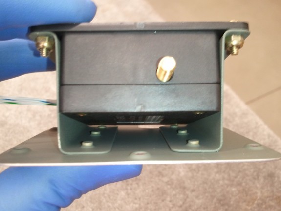
I decided to install the servo Z brackets with NAS1097 rivets in the last 2 aft holes. This allowed me to countersink the holes rather than dimple and still get good clearance of the servo when installed. It is tight, but clears. 0.032″ skins are just enough for AD3’s. I was careful to not over countersink but it was close.

Right where it Should Be

As mentioned in the prior log entry, the location of the servo per the plans is not right. As you can see here, I located it where it does belong and the jack shaft of the servo lines right up where it belongs. I do not like that they want you to have the wires exit in the same hole so I may open up a 3/8″ hole just above (below in this picture) the jack shaft hole, to route the wires for the servo through to avoid any interference.

Fits as it Should

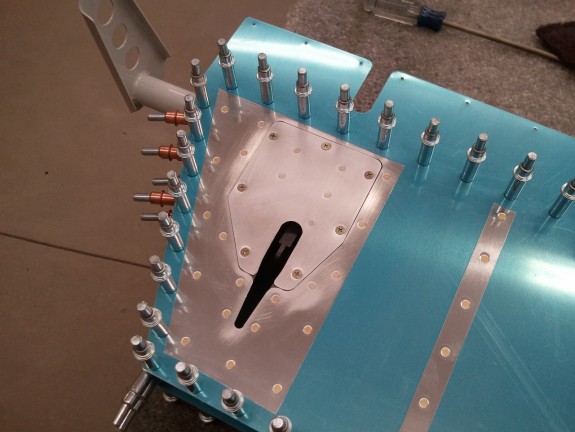
Trim cover plate installed. You can see the arm of the servo is right in the middle of the slot and ready for the tab. Looks good to me. Now I have to take it out and start match drilling the skins to the skeleton and prep for the trim tab assembly. The other item I need to think about is how to hookup and where to route the trim servo wiring. I have a few ideas…we’ll see how it ends up down the road.

Categories: Elevators

What is Drawn != To What Works…Sometimes

October 31st, 2011 No comments

How it is "Supposed" to be Done

In the spirit of doing something little any chance you can, I decided to work a little on the elevator trim servo/mount/cover tonight. I am using the electric trim option as I love it in the CAP planes I fly. Not to mention, I will more than likely add the auto trim feature in conjunction with the auto pilot I want to install too so electric trim is required. It may be overkill, but heck…I am building MY plane.

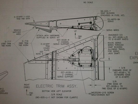
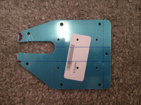
So I studied the plans that outlined how and what I needed to do to mount the trim servo. I made certain that I remembered that I was looking at the outside of the cover/inspection plate in the plans. I did not want to accidentally measure where to mount things by reading the dimensions relative to the outside and mark them on the inside wrong. As you can see from the plans, you are to measure from the outboard side of the cover 1 3/8″ in and 3/8″ in from the forward edge. This is then where you put the inboard forward edge of the left servo bracket (EET-602B-L).

I grabbed my ruler and then began to mark the cover with the measurements outlined.

That Seems too Far

You can see here that the “upper” line is the line represented in the plans that should be 1 3/8″ from the edge. Basically, set the plate face down on the plans and then flip it up so it is a mirror image. Right off the bat it was clear that this was not right. The line seems to be nearly centered in the slot for the servo arm. Referencing the plans again showed it really should be offset a bit. Clecoing the servo to both mounting brackets and setting it on the cover confirmed this as well, the output arm of the servo was not centered in the slot as the plans show.

I scratched my head a bit and thought…what if they really meant 1 3/8″ from the other edge and just marked it wrong on the plans? With all the flipping and translation to the part you have to do with the drawing, maybe they made a mistake…though unlikely. I also did a search on vansairforce.net to see if others were having issues with this drawing as well. The search returned a few replies that led me to believe the unlikely was true.

What the heck, I have not drilled anything yet, so I drew another line from the other edge and lined up the inside edge of the EET-602B-R and interestingly enough, the servo output was dang close to center in the slot. I think the draftsman did actually reverse the part.

Clamped and Ready

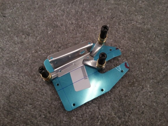
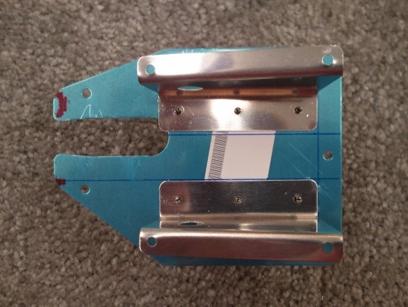
With the bracket confusion now settled and the correct orientation determined, I clamped the EET-602B-R to E-616PP. Having learned to not back a hole you are drilling with your finger, I used  block of wood behind the hole I was drilling and match drilled the bracket to the cover, clecoing as I went. Once that was done, I clecoed the servo and other bracket back on and then clamped the EET-602B-L on and repeated the process.

That is Better

Once complete and both are clecoed on, you can see that the EET-602B-L reference line as outlined in the drawing is indeed off by about 1/16 of an inch. It may not seem like a lot, but it will make a big difference if you were to follow the plans. I have read that some have just followed the plans and had to widen the slot for the arm, and others just replace the cover and do it again by eye. I recommend however you simply measure from the other side and line up the opposite mount bracket and you should be OK.

That is More Like It

All said and done, the servo output shaft is right where it should be. The last problem is that the aft two rivets that rivet the servo mount brackets to the cover may actually cause the servo to sit proud of the mounts because the shop head/dimples may contact the case. I may countersink the last two to avoid this. I have heard that some have made shims for the servo while others smash the heads a little more to clear the servo. Neither seems correct to me as one moves the servo alignment and the other weakens the assembly, granted, not by much. Stay tuned for the solution.

Categories: Elevators

Left Elevator Begins

October 29th, 2011 No comments

Ready to be Match Drilled

With the right elevator now closed up, the manual has you move on to the left (or harder) elevator. They note that it is a little harder because of the complexity of the added trim tab that is part of this assembly. I still had some time after finishing up the right closure so I grabbed the parts for the left and began to  assemble. I began with the spar, added the reinforcement plates and plate nuts. Worked on the outboard ribs and counterbalance drilling. Added the spar for the trim tab, the root rib, and the skin. It is amazing how quick it goes when you have done it before.

Back Side of Left Elevator

After about an hour, the left elevator parts were all clecoed and ready to match drill. I decided to call it a day. I will hopefully match drill this some time next week. I cannot believe I am almost done with the empennage major work. However, what is left is some of the harder parts to do right…so I am going to pace myself.

Categories: Elevators