The replacement E-709 rib arrived on the 27th and as soon as I got home, I went right to getting it prepped. I first reamed out the four holes on the forward flange and then dimpled the holes with my pop rivet dies to be safe. I then clecoed it into the elevator assembly as I had left it on Saturday. I was able to match drill it to the skin and to the horn. I then removed it, dressed the edges, dimpled it and then shot it with primer. Took about an hour to complete all the steps. I then dimpled the rest of the skin where the E-709 goes. I then disassembled the parts again and set them aside and ready for the next build session.
Friday was a busy night with Halloween parties so I was unable to get the skeleton finished. No worries, it was all ready for assembly for my build session today.
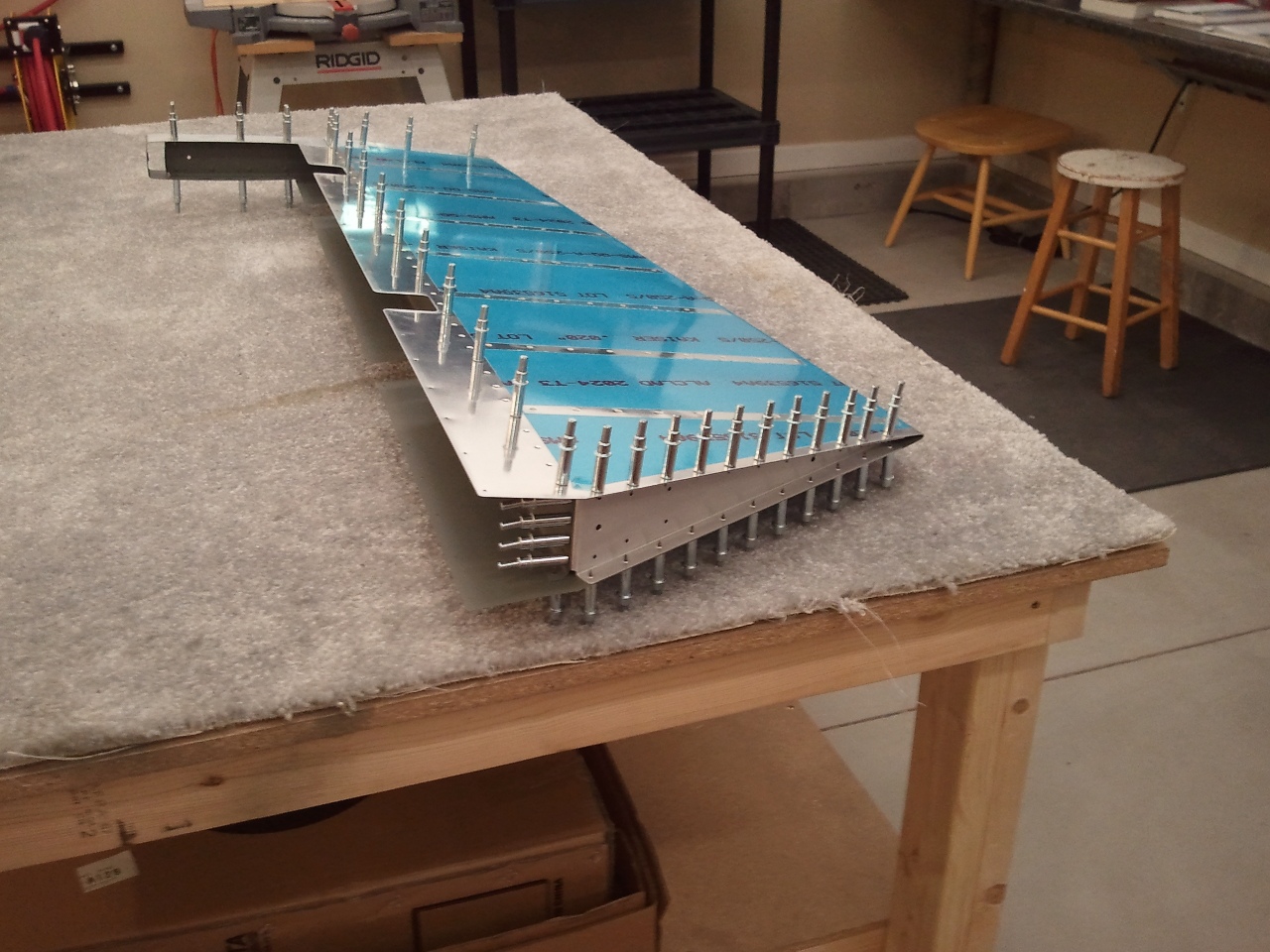
As soon as the sun was up and breakfast was done, I ran out to the shop. I joined the new E-709 to the E-702 spar and then riveted on the the WD-605-R-1. The skeleton was complete now. I then added RTV blobs to the ends between the trailing edge portion of the interior stiffeners. The idea is that it ties them together and dampens vibrations. Apparently some builders have reported cracks in this area after the plane has flown for some time. Hopefully this helps counter/eliminate this problem.
I inserted the E-714 counterweight previously milled down in the nose of the E-713 skin and then inserted the skeleton. I then clecoed it all back together for the final time. Now it was time for fun. I final riveted the E-703 and E-704 ribs to the E-713 skin on both top and bottom. I then continued along the E-703 rib to the second to the last hole with my pneumatic squeezer. The last holes near the trailing edge are just too tight. I then did the same along the root E-709 rib. Then I did the spar. With the squeezer, you can move along pretty good. The final riveting took no more than 30-40 minutes to complete. As for the last trailing edge holes on the outboard and root ribs, I simply used some MK-319-BS blind rivets and called it good. Better to fill the heads with body filler than have to repair an entire panel with the stuff.
I then added the washers and nuts to the counterbalance weight. I still need to torque them, but the weight is attached permanently now. The right elevator is now closed up. I then taped off the E-713 counterbalance skin forward face and filed the counterbalance weight to the shape and profile of the skin. It still needs a little more shaping to be ready for the fiberglass tip install…but I will do that when I get to installing them. As you can see above, it is nearly done. Now that is progress. 🙂
Since I mangled up the E-709 rib on Friday and then ordered one that night…I needed to get something done. So I disassembled the right elevator and got everything prepped for primer. I dimpled the spar and outboard ribs and the skin. I did not dimple the holes in the skin where the E-709 goes because I wanted to be able to match drill the new E-709 after it arrived.
It was a nice day, so I ended up getting everything primed by mid day. I took care of a few “Honey-Do’s” while the primer dried.
When the primer was dry, I assembled and riveted the E-702 and the E-610PP/E-611pp reinforcement plates and the corresponding plate nuts. I also riveted the E-703 and E-704 ribs together and then to the E-702 spar. At this point I would have riveted the e-709 root rib to the E-702 spar and then the WD-605-R-1 to the both of them, but…the prior post outlines why that was not happening.
At this point, I was at a standstill because I had no parts left to continue…or so I thought. There are two rivets on both the top and the bottom of the E-713 counter balance skin and the E-701-R skin that tie the two together that are not joined to any other parts. If you forget to get these and join the skins to the skeleton, you will not be able to get to them. I chose to do these now.
At the end of the day, I had a mostly completed skeleton and skins ready to go together. For grins, I clecoed them back together just so I could feel like I had done something. They are now ready to accept the new E-709 when it arrives and then I can close this elevator up.
The instructions say in order to join the right elevator Spar (E-702) to the root rib (E-709) you have to use flush (AN426) rivets so that the elevator horn (WD-605-R-1) can lay flat against the spar at the joint. To do this, they say that you need to countersink the forward face of the E-702 spar for the flush heads for the four holes that join it to the E-709 rib. Another option that Van’s says is OK is to dimple the E-702 spar and the E-709 flange instead. Really, these 4 rivets are simply nailing the flange of the E-709 rib to the E-702 spar but most of the strength is handled in the Elevator Horn that also rivets these two parts together at the corner.
With that said, I chose to dimple these over the countersink. After all, the dimple keeps the full thickness of the parts and should be stronger. Dimpling the spar was a matter of putting the dies in the DRDT-2 and smashing away. The rib flange is another story. It is bent past 90° and thus makes it tough to get the dies on the back side much like the trailing edges of the skins for say the elevators and ribs. Typically, I would grab my pop rivet dies here and squeeze away. However, I had just purchased a tool that I thought…heck, that should work here.
Made to Help
Here is the tool. Basically, it is a female die for a AN426AD3 rivet set in a bar so you can reach in to close spaces. You then take a rivet set with a hole in the end that will accept the male die and grab the rivet gun. Then you line up the pilot of the male with the hole and the female die. A few taps from the rivet gun and you should have a nice dimple in a tight spot. Sounds easy enough right?
Remember when I posted about my shop air supply setup? Well, it turns out that my brilliant setup bit me. Part of the setup to use the tool above is setting the pressure right on the regulator for the rivet gun. The various pneumatic tools I have all use different PSI settings. I ran over to the regulator, excited to try my new tool, and dialed down the pressure to about 30 psi. I ran back over to the bench, lined up the pilot, hole, and die. I took a deep breath and squeezed the trigger. Almost immediately I thought…”Man, this thing is hitting really hard!” At that point it was too late. I had ruined the flange of the rib. It hit sooo hard, it cracked the rib near the radius bend. I immediately slapped the forehead and reprimanded myself for again not testing a tool on scrap first.
Well…that part was scrap now anyways…so let’s at least get it right for the future. I could have just made a doubler out of scrap and perhaps made a scab flange and salvaged the rib, but empennage parts are cheap and I needed to place an order for some stuff with Vans anyway. So I went back over to the regulator and dialed it way down and tried it again on the next hole. Funny thing…it hit just as hard again. I was starting to thing something was wrong with the regulator or my rivet gun. I tried turning down the flow at the gun and hit the third hole. Some improvement, but still hard hitting.
Tried another setting change and still…this gun is hitting really hard. The regulator was way down on PSI, the flow was down…what is going on? I grabbed some scrap and drilled and deburred some #40 holes and kept trying with no luck. In frustration, I looked again over to the wall and then realized my error. My hose was still plugged into the Tank Pressure Outlet. I was running 135 PSI through the gun. In all the time I was setting the regulator, I never noticed that I was plugged into the unregulated side of my setup.
Immediately, I began to wonder…did I just ruin my rivet gun? Did I bend up some dies…what else? Once I moved my hose over to the correct outlet, dialed up the regulator and flow, the remaining tests proved to work. The tool works great…if you are set up right. Doh!
So…I needed to order up a new E-709. That killed my chances of getting the right elevator complete over the weekend. I decided to try my skill of stop drilling the cracks to make the most of the mistake. It turned out good. I still had things I could do over the weekend, so I set everything aside and called it good for the night.
One of the items on the plans I was wondering about, and was coming up in building sequence of the right elevator, was the E-714 counterweight trimming. As designed, Vans incorporated a counter balanced tail surfaces to give the plane a very neutral feel on the stick and to eliminate/reduce surface flutter. This is accomplished by placing a weight on an arm located in front of the hinge line. There is a counterweight in both elevators and the rudder.
There is a catch however. The right and left elevators do not weigh the same. One has a trim servo and trim tab in it while the other does not. Vans ships 2 cast lead weights for the elevators that are the same shape, weight, and size. This means that on the lighter elevator (right side) the counterweight must be reduced in mass compared to the left. The plans have a nice full scale drawing of what the weight should look like when trimmed. Here you can see my finished product overlaid on the drawing.
The trim poses a few problems. It needs the radius and is thick and dense (though soft) and I was not sure how I was going to do it. A hacksaw and a file perhaps? That is a recipe for disaster. Then it dawned on me…I know a machinist who does very accurate work with a part and a drawing. He will know what to do. So my buddy (son-in-law to the machinist) called him up and asked if we could run over to his shop after the Cub Scout pack meeting for our boys. He agreed. Within 10 minutes of arriving, he knew exactly how he would achieve the trim.
Basically, he made a knife for a fly cutter that incorporated the radius of the cut. He chucked it into his milling machine, clamped the counterweight in, referenced the distances, and started up the mill. He took 3-4 passes at the weight taking a slice off the back each time. As the depth increased, the radius appeared. He checked the size a couple of times with his calipers, and then set up the last cut. Once done, I had a perfectly flat, trimmed back, with a perfect radius exactly 1/8″ from the shoulder of the front…exactly per the plans. Total time, 20 minutes and we watched the mill do most of the work. I love this guy! Having done machining for 40 years…he knows his stuff. Thanks Len!
Ready for Installation
Here is the counterweight ready to install. One less thing to worry about and out of the way. Remember though…do not modify the other side the same way. I have heard some builders have. The part is not expensive to replace, but is expensive to ship! 🙂
I spent some good time on Sunday researching and understanding the “Bending Brake” that Vans suggests be made in the manual. Several builders noted that the brake as outlined allowed for too much flexing in between hinges and to add more. Another debate was whether or not to leave a gap in the boards where the hinges were. I could not come to a clear dimension or necessarily the need for a gap. The last debate was if it was advantageous to use a dowel in the trailing edge when compressing the skins to insure the brake did not smash the trailing edge during the bend. You can see now, with all the “debate” why someone may worry a little when attempting to do a seemingly simple, but critical step. So here is what I decided;
Make the brake out of 2×8 premium lumber. One half is exactly 60″ and the other was 54″. This gave side handles to the brake itself.
Use as many hinges as practical. The number ended up at 12 – 3″ hinges.
No gap in the boards at the hinge line. I did however bevel the corners a hair to give the hinge barrel some area to clear.
3/16″ Dowel in the trailing edge while squeezing to hold the radius (3/32″) in place while smashing the skins.
For family night, we piled into the mini van (friend calls his a “Swagger Wagon”) and went out for dinner. We then hit Lowes Aviation Supply for parts. We took in some of the Christmas Decor that was out for sale already. I know…nuts isn’t it? I picked up the nicest 2″ x 10″x 10′ plank I could find, a 3/16″ dowel, a 1/8″ dowel (just in case), and the hinges. A couple of other incidentals while we were there and back to the house we went. I then headed over to a neighbor’s house because he has some nice saws for woodworking. I cut the plank to length and dressed up the edges a bit.
Complete and Ready to do Some Damage
Here is what I ended up with. I center drilled all the holes for the 12 hinges (72) and then mounted the hinges with the screws provided with the hinges. Interestingly enough, each hinge also came with a 3″ screw in addition to the six standard sized ones. Rather than waste them, I chose to countersink the face of the break and drill and screw the brake to my build table. So at each hinge, there was a 3″ screw holding it down. Needless to say, it does not move. With 12 hinges, it takes a little pressure to actuate the break. Translation…no slop. Once attached to the bench, I sanded the interior faces using my orbital palm sander to insure no bumps or potential dent makers. OK…we are ready to destroy parts now.
3/16" Dowel in Place...Deep Breaths...Ready to Smash
After some deep slow breaths…it was time to get smashing. Here you see the dowel taped into the trailing edge. The theory is that it backs up the bend to keep the radius intact while you are squeezing the skin together. The logic was sound so I incorporated it. OK…moment of truth. Time to slide the skin into the brake and push.
That was not so Bad
Once the skin was in the brake and the trailing edge was against the barrels of the hinges, I flipped the top over and taped the skin edges down to the lower part with “Gorilla Tape” and started to push. I noticed that my pushing was not doing much. I stepped back and realized that I needed to back the trailing edge away from the hinges a tad. Perhaps this is the theory behind the gap in the boards. Once I backed it out about 1/2″, I could see that the bending was starting to occur. I then moved it out 1″ from the hinges and pushed. Again, it bent a little more. It was getting close at this point. I decided to flip the skin over and back it off another 1/2″ and really push. It took me standing on a stool and kneeling on the brake to really get all the force I needed to close the skin together. I was a bit surprised actually. I periodically checked the trailing edge and when finished, was pleased to see a straight and nice radius at the bend. I did have to take the dowel out for the last application of weight to get it a little more closed up, but all in all, it worked and was not that bad. I repeated the same procedure on the left skin.
I may need a tiny bit of massaging to get absolute perfection, but as they are now…they will do just fine. I will evaluate down the road if the massage is really needed. These turned out pretty dang nice.
I inserted the spar in the left skin and the root rib to give the skin some rigidity and then placed it on a shelf. The manual has you work the right elevator first because it is a bit simpler since the trim tab is in the left. So I brought in the skeleton I had done some work on prior to bending the skins. It slipped right in and lined up like a dream. I clecod the skin to the under structure and then match drilled the control horn.
Ready to Match Drill and Disassemble
At this point I simply need to match drill the skin, deburr, dimple, prime, and assemble. OK…not true…but close. Rather than chance a mistake, I closed up shop for the night.
Not too many pictures today. I took care of a few “Honey-Do’s” and then headed to the shop. With all the parts primed and ready to back rivet the stiffeners on, I went to it. I like back riveting, it goes fast. Set the gun up, tape in the rivets, stack the parts, and smash them together. I knocked out the stiffeners and trim access doubler pretty quick. The next thing in the manual is to bend the skins shut to then attach them to the skeletons. I am very nervous about that step and have yet to build my bending brake so I was near to a standstill. I decided to start on the Right Elevator Skeleton as far as I could before needing the skin post smash.
I was able to fit the counterbalance weight in the skin and begin the skeleton assembly. I drilled the counterbalance weight and match drilled all the plate nuts for the hinge points and prepped the ribs in the counterbalance. At the end of the day, I had a skeleton that was match drilled as much as I could before needing the skin. I guess it is time to study up and get the brake made and make the “bend!” I’ll read up on it tomorrow and maybe tackle it on Monday after family night.
For some time, I knew the time was coming that I would need to install some nut plates to hold some screws that hold down things like access plates, fairings, etc. One of these places appears on the elevators. There is a doubler on the left elevator that allows for access to the trim actuator, be it electric (what I am doing), or manual. Basically, the doubler creates a flange inside the elevator skin that an access plate then screws into closing up the hole flush with the elevator skin. You find these access holes all over planes so you can service the aircraft in the long term. The trick is, that on a plane where flush rivets are used, you want your access plates to also use flush type fasteners. This requires dimpling the access cover and using flat head screws. Nut plates can be used with either as they are designed with a recess to allow for a dimpled doubler or can simply be attached to a flat skin to provide a nut on the backside. In all cases however, the fasteners that attach the nut plate to the airframe must be flush so that the access panel can lay flat against the doubler.
One of the things that I read up on was how people install their nut plates. There are two methods that work. One is to dimple the skin and the nut plate to accept a standard AN426 rivet. The risk here is that you can really mangle the ear of the nut plate as there really is not much material on them to dimple. The other is using NAS1097 rivets. These have the same shank size as their standard AN426 counterparts, but they have a shallower head. Since my local supplier required a 1/4 lb minimum purchase of each size at nearly $90.00, I found a kit by Avery Tools that met my needs. It has 2 different diameters with 3 lengths at 3/4 oz of each. You can buy many of these kits for the $90.00 required for one size. I think it will hold me over for many a nut plate.
Side by Side of Shanks
What is the advantage then? Well, instead of having to dimple the skin and the nut plate, you simply can countersink the skin very lightly and then insert the rivet in the hole and nut plate ear, and smash away. Since the rivets on the ears are simply keeping the nut plate attached to the assembly and keeping the plate from turning when a screw is inserted, the fastener is really only working in shear, not tension. As you can see from the picture above, the shanks of the rivets are the same across the diameters. You can also see that the shoulder of the rivet head is much more shallow. Where countersinking may cause a knife edge with a standard rivet (countersink goes to the backside of the sheet), you can countersink thinner material and still get a flush head. Again, the force is in shear when you are screwing in a fastener to the nut plate, so the shank is the more critical portion of the rivet.
Side by Side of Heads
But wait…there is more to these. Say you are doing an assembly that requires 3/32″ (AD3) rivets and you bugger up the hole they go in really bad? In that case, you still have some saving grace. Notice in the above picture, that the head of the NAS1097AD4 is the same diameter as the AN426AD3! You can replace the AD3 rivet that is now undersized with NAS1097AD4 and from the top, you would never know it was different. Now…you cannot do this to all of them in a row mind you…but 1 in 10, you will be OK. That is why these rivets are referred to as “Oops” or “Fixit” rivets. As it turns out, I had exactly that happen to me as I was back riveting one of the elevator stiffeners. The AD3 did not set very well and when I drilled out the rivet to replace it, I noticed that the hole was now too large for a new AD3 but I had good edge distance, so I opened it up to a #30 and slipped in a NAS1097AD4. I am not telling where and you will never know once the elevator is closed up!
NAS1097's at Work
Here is the trim access hole with the doubler in place. You can see I have inserted the screws into the nut plates center. The NAS1097AD3’s are on either side of the screws. You can also see the difference in head diameter with the standard AN426 rivets that hold the doubler to the skin. They have the exact same size shank. A simple turn of the debur tool can produce a decent countersink, but I chose to use another little jewel I picked up with the rivet kit.
Could Prove Dangerous!
Basically, it is a chucking adapter with a threaded female side so I can thread in my countersink/debur bit into it and chuck it in a drill. This allowed me to more accurately and lightly countersink the doubler for the smaller head. Once all the countersinks were done, I hit the doubler with a shot of primer and let it dry. Once dry, I back riveted the doubler to the skin and then went back to prepping the stiffeners and skins for primer and back riveting.
The weather in Utah is changing fast. This could be the last week of really nice temperatures outside. So when I got home from work, it was straight out to the shop to get the skins and stiffeners ready for primer. After all, I needed parts ready for a build session on Saturday. So I spent the remaining 70 degree daylight hours shooting primer. Here are the right elevator parts drying. I repeated the same for the left. Armed and ready for the weekend. 🙂
After work, I had some free time, so off to the shop. The first thing I tackled was dimpling the trim servo doubler (E-615PP) screw locations with my #6 dimple dies in the DRDT-2. These holes are REALLY close to the edge of the part, but they came out nice and crisp. I then swapped the dies for my 3/32″ and then dimpled all the rivet holes except the rivet locations for the nutplates that will be attached to the doubler that hold the screws for the access cover to the trim servo. I have decided to use NAS1097’s here instead of trying to dimple the doubler and the nutplates. These are commonly referred to as “oops” rivets. Why you ask? I will post more about them later when they arrive.
The next item to hit was removing the vinyl off the outside and inside of the skins at the stiffener locations. I have decided to do what I did on the inside of the rudder with the inside of the elevators. I removed the blue vinyl where the stiffeners go, and then I will scuff those locations and prime. Then when I am ready to close up the skins I will peel the rest of the vinyl off and lightly coat the rest of the interior of skin with some primer without scuffing. This appeared to work well on the rudder skins, and gave it a hair more corrosion resistance.
Once all the vinyl was removed, I dimpled the skins in the DRDT-2 and the stiffeners with my pneumatic squeezer. I then cleaned up and re-labeled all the stiffeners. All that is left is scuffing the inside areas of the skins and to prime them and the stiffeners. Then I will be ready to back rivet these little buggers on. With the weather warming up for a few days, I just might get it done this weekend.
One of the reasons I love working for a bank is the extra week of days off. Columbus Day is just one of those occasions. I am starting to get a real collection of air plane assemblies and need to find a way to get them up and out of the way. I have some ideas, but rather than tackle that right now, I decided to get started on the Elevators with my free time.
The first thing to knock out is getting the stiffeners cut to length and then trimming to specs. Here is where having the right tools makes quick work of a tedious task. I simply took my snips and trimmed to nearly the rough shape. Then I hit each with my 12″ disk sander to finish up the ends. As for the tapers to fit in the trailing edge, I took my band saw with a new blade and trimmed them to close to the cut line. The new blade went through these like a hot knife through butter. Once close, I went back to the sander and cleaned them up to the trim line.
Stiffeners Tapered and Scuffed
All that is left is to then hit the edges and round the corners to final shape and deburr. My scotchbrite wheel made quick work of this task. After they were to final shape, I simply scuffed them in prep for primer now. I like to get the not so pleasant tasks all out of the way at once. At this point, they are now ready to match drill to the skins.
Ready to Match Drill to Skins
Here they are getting ready to be clecoed to the skins. There is one for the top and bottom of each skin. I took some time to label each before drilling so I could relocate them to the same spots once the drilling was complete.
Time to Match Drill
So here are the two skins ready to get at the match drilling. The skin shown on the right is s a little different. It will contain the electric trim servo and trim tab. It has a doubler/reinforcement that is match drilled at this point as well. So I went to using a #40 chucking reamer and matched all the holes….except…the last holes in the trailing edges that were not pre-punched in the stiffeners. I am not real sure why these are not pre done other than perhaps in providing the stock to make the stiffeners, it is easier not to since there is a slight difference in the length of some of them between the right and left halves of the elevators. That, or builders could confuse them when building and ruin them. Either way, there are 3 holes in the skin on each side of the skin that need to be used as a template to drill the final holes in the stiffeners. So I chucked up my #40 bit and got to it.
Joined the "Club" Bottom Side
Then I found out the reason these are not pre-punched. Apparently there is a list of “clubs” or initiation rights an airplane builder has to join/pass to be full fledged. One of those is to drill your finger at some point. In Van’s great wisdom, they created a perfect storm to help you accomplish one of these rights. I was reaching in to hold the stiffener to the skin from the backside and drilling from the other side. This means you are essentially drilling blind to the backside. I thought I had gauged my distance from the hole further on down the stiffener well enough. At his point I had made it through 9 of the 12 holes that had to be done this way. On hole 10…something felt very different as I broke through. It then dawned on me…that is my finger!!!
Joined the "Club" Top Side
Now that I realized that my #40 bit was now in my finger, I backed the drill out and extracted my hand from behind the skin. Yup…there it was…my entry into the “club.” I went though most of the meat of the end of my left index. I stopped just short of making a hole in the nail. As you can see…that is all the way through. I actually did create a hole in the nail but it did not break away. Fortunately my bit is very sharp. I stopped just in time to keep it from tearing out any meat so in reality, I simply created a deep spiral cut that when the bit was backed out, it closed up and stopped bleeding pretty quick. I irrigated it really well, threw a bandage on it and went back to the last 2 holes.
Once the match drilling was complete, I removed all the stiffeners, deburred all the holes in them (not the skins yet) and cleaned up the trim servo plate. They are all ready for dimpling and priming now. I will then need to deburr the skins and dimple them and then prime the inside. We’ll see if this hole in my finger slows any of that down.
Once the trailing edge was dry from the tank sealant applied Thursday, it was time to close it up. I was still a little nervous about the double flush riveting that had to be done. The manual does a good job describing the procedure, but it is still somewhat daunting. I decided early on that I wanted to alternate the manufactured and shop heads side to side for balance. May seem trivial, but I wanted a more symmetric appearance from side to side.
I pulled off the two angles and clecos and was pleased to see a straight trailing edge all glued up. I had a bit of cleanup to do with MEK to get the oozed sealant off the skins. There was a bit in each hole as well. I simply ran a #40 bit by hand through the holes to get the sealant to break at the edges of the holes and pulled out the little ball. Some of the dimples were filled so I lightly ran a countersink bit in them and it cleared it right out.
Now that it was all cleaned out/off, I set a rivet in every other hole and taped them in. I then flipped the rudder over and made my first mistake. I put my mushroom set in the gun and started to “half set” the tails starting from the middle of the rudder and working my way out alternating the sides from center. The mistake was using the mushroom set. It is simply the wrong set to use at this point. About halfway through setting these, the set slipped and I dented the skin near the spot where the skin and the AEX wedge meet underneath with the heal of the mushroom set. At this point I should have realized I was not using the right set. I did it once more and then figured out what was wrong. Filler at paint will hide the dents just fine but it was still aggravating.
Once I realized I should have been using my back rivet set to “half set” the tails, all started to flow. I simply angled the set enough to push the tail into the center of the dimples and then rotated the set to be parallel to the skin. The head of the set never came close to the skin…duh! I got all the shop heads set, and then flipped the rudder over. NOW you put the mushroom set in and smack the manufactured heads over the back rivet plate. After a few…I realized I was getting it…too bad it took some dents to get there.
Once all the rivets were smashed into the dimples completely, I repeated the process with the remaining holes with the manufactured heads on the same side of the “acorns in the dimples” now complete. You can see the result above. They look great and the trailing edge came out straight and within tolerance per the manual.
Looks Done to Me
Here is an overview shot of the rudder trailing edge complete. Nice and sharp and pretty straight. The next step was to then roll the leading edges to complete the assembly.
Leading Edge Rolled OK
I wanted to get a nice clean joint along the leading edge. Prior to rolling them, I decided to use a nifty tool I got from Cleaveland Tool that forms the edge of material that will be lapped over another sheet. Basically, it bends a very gentle lip on the edge of the sheet so that when the two sheets are overlapped and then riveted, it makes a nice tight joint. I learned another valuable lesson here. NEVER try a tool for the first time on an assembly. Either mine is defective, or I do not know how to use it…but I mangled up one of the tabs on the top overlapping skin of the leading edge portion. Basically, the roller of the tool with the lip on it did not ride the edge as it is designed, but it rolled past the edge of the tab and made a mess of that edge. I was simply deflated. NEVER EVER use a tool on a part until you have mastered its use. I was able to get most of the mess out by using a wooden block with a slot cut in it about 1/4″ deep to straighten out the mess the tool made and then hand bend a flange in the tab…but the Cleaveland tool had stretched the metal in some places that was simply not going to be 100%. Aggravating to say the least. I will be practicing a TON more on scrap with this tool before it ever touches my plane again. The video below makes it look easy…mine did not work out so well.
I did not take too many pictures of the rolling procedure. Basically, I took a method I saw on Vansairforce.net which used some “J-Bolts” and a pipe. Instead of using the “J-Bolts” I used “U-Bolts” that could be locally sourced. First, you duct tape the skin edge to a section of 3/4″ metal electrical conduit. I used gorilla tape. That stuff beats duct tape hands down. Then once the pipe is taped to the edge, you “U-Bolt” the pipe, with the skin you are rolling face down, to the bench leaving enough slack in the bolt tightness so the pipe can be rotated. The “U-Bolts” hold the pipe to the bench at the hinge locations allowing you to twist the pipe and roll the skin all at once. As you twist the pipe, the control surface will slide along the bench as the skin is rolled. It worked great. I was left with a decent radius on both skins.
After the skins were rolled, I simply clecoed them together and worked the radius a little more by hand. Then I match drilled and deburred the holes to a #30. Here is where the mangled tab edge created earlier showed its problems. Many builders report little puckers between the rivets when the finish this part. Mine did the same on the center tabs. If I had not had issues with the edge forming tool, I think I could have had a really nice overlap on the center section. Needless to say, where the metal was stretched by the tool, my puckers are not pretty. The upper and lower overlaps look pretty good. Either way, this particular area will NEVER be seen unless the rudder is removed from the plane. Even at full deflection, you cannot see it, so…I am calling it good enough for now. At 200 mph and FL20, it will not make a difference in flight. If it REALLY bothers me when the plane is ready for paint, I may build another rudder. Unlikely as this one looks good otherwise and is very structurally sound.
Rudder Complete
We end the day with a glory shot. I had a conference meeting to attend after the build session and my lovely photographer was busy all day. So I convinced her to take a picture of the finished rudder right before I left. I think I may have the record for the most cleaned up glamor/status shot out there. All in all a good day. The fiberglass tips are all that remain. Time to get started on the elevators now.
After a record breaking weekend of flying the “Spam Can” Sundowner for my Birthday, the family needed to recover. I was not looking forward to gluing the trailing edge together using the Flamemaster sealant I was able to procure locally. I have heard it is nasty stuff and hard to work with. The time came however and the night’s schedule was open so I figured, what the heck…time to get it over with.
I had already taken the time earlier to make up two pieces of aluminum angle to support the trailing edge during glue up and cure. The plans call for only one, but I chose to double up so that I could cleco from both sides of the rudder and have something to grab into. Additionally, the two stiffeners insure that the clamping force is evenly distributed to both sides and both skins.
Fancy Tank Sealant Cartrige
So now the moment arrived to get the sealant mixed and applied. I followed the instructions per the package and turned the white tube black. I do not have a dispensing gun yet so I simply took a piece of 1/2″ PVC pipe to push the plunger from the back and squeezed out enough on a paper plate. I then used a Popsicle stick to spread a thin even coat on both sides of the trailing edge AEX wedge. Be sure to wear some form of disposable glove when working with this stuff…it is sticky and very messy. Also make sure to remember which way the AEX belongs in between the skins. You do not want to have to take the AEX out and flip it after this stuff is on it.
Once the AEX was smothered and back in between the skins, it is time to take some MEK and wipe down the globs that may have squeezed out from the rivet holes and the trailing edge of the skins. I additionally took the tail of a #40 bit and pushed it through each hole so I could wipe it from the other side and free up the hole for clecos and eventually rivets with little mess.
I then reinstalled the aluminum angle on both sides of the trailing edge and clecod every other hole starting from the middle and worked ever other side of the middle out. I figured this would line everything up and keep it straight as it was squeezing the goo out. I then flipped the rudder over and clecod the other side the same way. I felt that this was a good way of truly getting the same clamping force on both sides. It appears to work fine. I then hit the trailing edge with a MEK soaked rag to clean up the little that was collecting between my two aluminum angles. As the picture above shows…it is pretty darn straight. Excellent!
Curing the Sealant
Once the assembly was wiped and clecod, I needed to set it aside so that it could cure. I noticed when assembling the rudder for riveting, that once the counter balance was installed, the rudder would get a slight twist in it sitting on the bench. I shimmed the counter balance when doing the perimeter to minimize the twist and it seemed to work. I also saw the slight twist when I slid the gooped up AEX. To eliminate the twist all together while the rudder was curing, I decided to mount the rudder vertically on the bench. so that the counter balance was pointed down and thus removing the problem. Here you can see the setup. I simply put clamps on either side in case it decided it wanted to fall. The carpet did great at allowing the non bent leading edge of the skins to sink into the carpet while the bent edge stayed afloat on the surface. They sat pretty level and allowed the rudder to sit vertical on the bench at rest. Here the rudder will sit for a couple of days curing. Once cured, I will then set the “acorns in the dimples.”