Left Spar Nutplate Countersinks Complete

April 25th, 2012 No comments

Chatter Free Countersinks

I was able to get some time in the shop tonight and continue the prep work on the Left Spar. I needed to countersink the nutplate locations for the #8 screws that hold the tanks to the spar. Additionally, I needed to countersink for the #6 screws on the bottom that hold the inspection covers on. These countersinks are a challenge only because they are deep enough to open the hole wider than the pilot of the cutter and can allow for it to move around once deep enough. You have to use something beyond the flange to hold the pilot after it cuts the countersink beyond the flange. I have read several build sites that describe what can be done to accomplish this task. Van’s states that you can install the nutplates first and then use the nutplate as guide for the pilot of the countersink. That seemed a little hokey to me, but several builders said that it worked OK. I guess I just did not like the idea of possibly ruining the threads of the nutplate with the pilot of my cutter and the possible chips that could get lodged in between the nutplate and the spar flange.

Another option some have used was to use a piece of 1/16″ aluminum angle to back the holes that are to be countersunk. You simply clamp it to the flange and match drill the holes to the angle and then use it to keep the pilot centered in the hole. Since I had my angle from the rudder lying around, I decided to give this technique a shot. In the above picture, you can see that I have clamped the angle to the flange and have already match drilled the center holes with my #21 bit. I then used some clecos to hold it down the flange as I clamped it closer with some alligator clamps.

I then worked my way down the flange with my #21 piloted, 3 flute countersink. I tested the depth of the countersink in some scrap. I was aiming for a 0.370″ wide countersink (Van’s states it should be between 0.365″ and 0.375″ in diameter) and was spot on. As I would countersink, I would let the countersink cage nearly bottom out, then remove the chips, then finish the hole. This left a very nice, chatter free countersink. I figure that at .0370″ I can still adjust if needed, but many report that it will work great as is. As each was complete, I leapfrogged the two clamps so I could hold the angle tight to the flange.

How I did the Countersinks

Here you can see the angle down the length of the spar flange. The important thing is to not let it wander as the countersink is cutting. This is what eliminates the chatter.

The #6 Screw Holes In Works

Here you see the #6 holes for the inspection covers to spar interface. I used the same piece of angle to back these up. I simply offset the angle until I had no overlapping holes from the #8’s and match drilled them with #30 bit. I then used my #30 countersink cutter in a different cage set up to cut a countersink with a 0.312″ diameter. I found that Van’s recommends a countersink no greater than 0.3125″ for #6 screws. I tested on a scrap piece and then hit these. They come VERY close to the edge of the flange, but according to other builders, that is expected. Once complete, I was left with many shiny and chatter free countersinks that are ready for nutplates. The angle backer trick appears to have worked nicely. Now I simply have to repeat the process on the right spar. Thankfully, the angle I match drilled should line up with the holes already in it from this spar. I simply need to clamp and cut.

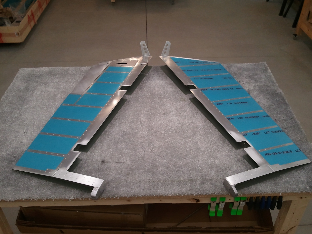
Left Spar Countersinks Complete

It was bed time for the kids and I just finished the countersinks and was cleaning up the shop when I got some visitors. My second son Alex is a real curious one, so we chatted a little as to what the gold thing was on the bench. I asked my wife to take a shot of me working/posing with the parts and he weaseled in the shot. Hopefully his curiosity sticks because I will need a bucking partner on the wing skins soon enough. With everything learned on the first spar, the hope is that the second will go a little faster.

Categories: Major Wing Sections

Wings Begun, Spar Countersinking on the Left Spar

April 19th, 2012 No comments

The Tank Nutplate Countersinking Begins

I had originally planned to take the day off from work to participate in a State/CAP exercise. The State of Utah decided that our assistance was not needed and they were going to spin down. So I had the day off…and I debated if I should go in to work or use it for fun. Fun it is. I spent most of the day building an empennage cart to store my finished tail parts in and get them out of the way. I will outline that in a separate update.

Once the cart was complete, I organized the wing kit crate parts and emptied the the crate. I also emptied the spar crate and pulled the spars out of the shipping plastic. After a close inspection, and only finding some minor nicks, I decided to start with step one of the wings…countersinking all the nutplate attach holes for the tank/inspection cover screws. So I chucked up my #40 piloted countersink in its preset cage, ran a test hole in some scrap, and started on the #40 holes on the spar flange of the left spar.

They are Gold in Color for a Reason

You can see here that I used some masking tape on the spar. This was to protect the GOLD anodization as well as keep chips from the countersinks from falling into the valley created by the spar channel and the spar bars. It works great. The spar is a work of art. It still amazes me that this chunk of metal can withstand +6 G’s. Engineers are cool. Once all the #40 holes were done on the top, I flipped the spar over and did the bottoms. I used my cordless drill on the low speed setting. More torque, no chatter. I tested all the holes by dropping a rivet in. Every one of them is perfect.

Nutplate Attach Holes Countersunk...in 1 Spar

I was able to get all the #40 holes done on the left spar and then the battery died on the drill. It was late anyway so I called it quits. I think I will use another trick I saw on the larger holes. Basically, I will match drill the larger holes with and #21 bit to a cheap piece of aluminum angle picked up from the local Lowes aviation supply. Then I will countersink the holes with my #21 piloted countersink to the correct depth for a #8 screw. The aluminum angle will provide more meat for the countersink pilot as these holes will end up with a knife edge on the bottom. This should eliminate chatter in these holes because the pilot will not wander as the hole in the spar flange opens up. Van’s has you install the nutplates and then use them for centering the pilot…hmmm.

We’ll see how it works out in the next couple of days.

Categories: Major Wing Sections

Preparing for Wings

April 14th, 2012 No comments

Building the Wing Stands

I have had the wing kit in the shop since it was delivered with the tail kit back in April of last year. I opened it up and did the inventory at that time too. It has been taunting me ever since. I have been researching several builder sites as to how they set up their shops for the wing spar stands. Vans has you make them from 4″X4″ wood posts that extend floor to ceiling. I did not like this design as it limits where I can set it up in my shop due to the over head garage door. That, and the wood could warp over time, though unlikely here in Utah.

I really like the setup Rudi Greyling from South Africa devised. Basically he made the stands out of 2″X4″ tubular steel and bolted them to the floor of his shop. I have a friend/co-worker that used to be a pro-welder. We chatted it over and came up with something very similar in design. Instead of using angle for the feet like Rudi did, we decided to make a foot out of the same tube and weld it on. Each post will be bolted to the floor with 2 bolts instead of 4 like Rudi’s design called for. Basically we cut a 45° angle on one end of the foot and 22.5° angle on the other side. This made a nice trapezoid shaped foot. The reason for the 45° on one end was to give a little more leverage to the foot on the side that the spar will hang on.

In the picture above, you can see my son Taylor and me cutting one of the feet out with a torch. My welder friend insisted he learn…and so he did. Taylor did GREAT!! My friend was impressed with his steady and straight cuts. We traded off cutting out all the parts and getting them ready to weld together. It took a good 2 hours with all the grinding involved. I was amazed the torch cut through 3/16″ steel tubing like butter.

Once all the parts were prepped, my welder friend tacked the feet onto the posts and then finished the welds. That man can move and does a really good looking job welding. I used some scrap flat bar stock to cap the top of the tubes. All I need is to drop a tool down the 4′ tubes and not be able to get it out. He let Taylor try his hand at welding too. He did OK. He then had me do a couple of beads and then he finished up. I think these will be very sturdy and work well. I still need to file them down and clean them up for paint, but the hard part is done. Thanks Russel!

On the way home, Taylor looked over at me and said, “That was cool!” Made all the aches and pain worth it!

Once cleaned up and painted, I will get them installed in the shop.


Categories: Wings

Rib Flange Straightener Built

March 29th, 2012 No comments

Per the RVator...My Version

When I opened the Empennage kit last year, a nice little freebie in the box was a copy of the 27 Years of the RVator. It literally is a treasure trove of knowledge of all the articles that the Mother Land (Van’s Factory) had done over the last number of years. While many of the articles dealt with items that the earlier builders had to deal with, it is good read for the information and practices. It is apparent when reading through the info, that Van’s listens to it’s builders as many of these articles on how to do this, that, etc. are now just incorporated in the newer kits. Thank you to all those prior builders for your work and contribution!

One of the articles I saw really caught my eye. It described this simple tool that builder Bill Gast made. I had heard of a mystical tool that one could build that would make the job of straightening the rib flanges to 90° a chore of joy.  Since one of the more tedious tasks on the wings is this rib flange straightening, I was all for making it less of a task if able. I read this article and set out to make my own version. Before I started, I also searched the forums over at VAF, like you should for most questions, and saw a few other versions with clearer pictures.

The trick here is having the right angle on the part that the flange gets pushed into (the anvil). Upon the advice of both the article and the posts on VAF, 11° seems to be about the consensus. With all the information in hand, It was time to construct a new tool.

Bill of Materials:

6″ x 20″ x 3/4″ MDF Plywood Base Plate

2″ x 4″ x 12″ Anvil with 11° undercut on one face. (Mine was actually a chunk of a 5″ x 5″ post that I cut to shape.)

1 1/2″ x 1 1/2″ x 30″ Oak stick purchased at Lowes Aviation Supply. (Note, my local Home Depot Aviation Supply had the same but it was two 1 1/2″ x 3/4″ x 30″ sticks laminated together.)

Cut a 3″ long piece to accept one bolt for the arms
Cut a 20″ long piece with a 22 1/2° angle cut on one end of the handle/pinch bar
The angle is so that the bottom of the pinch bar clears raised portions of the rib like lightening hole flanges.

3/16″ x 1″ x 36″ flat bar stock from the metal bins at Lowes Aviation Supply

I cut two pieces 12″ long for arms.

Two 1/4″ x 20 x 2 1/2″ Bolts

Two 1/4″ Nylock Nuts

Four 1/4″ washers

2″ and 3″ wood screws

After cutting the bar stock to the 12″ lengths, I match drilled on the drill press, the 1/4″ holes in both ends so that they would match exactly. I then radiused  the ends on the grinder and polished them smooth (No burrs to scratch parts or humans). I had some paint left over from a project years ago, and since the color did not matter, better to use it than toss it. I sprayed the arms for protection.

I then took all the wood, cut to length and with the angles cut into the handle/pinch bar and anvil, I ran all the exposed edges over a 3/8″ router bit on my neighbors router table. This makes the handle very comfortable to use. As for the other edges, I was there and the router table was setup, so why not.

I attached the Anvil to the Base Plate, centered on the the long axis of each, with some 2″ wood screws. I eyeballed the location of the metal arms on the handle (approx 4″ from the bottom) and center drilled a 1/4″ hole through it. I attached the arms with a 2 1/2″ bolt and washers on the outside of each bar and tightened the Nylock nut just shy of tight, allowing the bars to pivot on the pinch bar.

I then center drilled on both the length and height of the smaller 3″ oak piece for the other 1/4″ bolt hole, and attached the bars to it. Lastly, I positioned the small oak piece along the center line of the anvil until I had the pinch bar just proud of the anvil face. Essentially, this allows the pinch bar to fully push the rib into the corner of the anvil and the base plate without pinching the thickness of the flange itself. Once the position looked good, I attached the small oak piece to the anvil with 3″ wood screws.

There you have it, the rib flange straightener. I clamped it to the bench and did a quick test on a few leading edge ribs and it appears to work GREAT! Like all tools, it takes a little to get the feel, but with little effort, the flanges on the ribs turned out pretty close to 90° very quickly. I wish I had this when I was working on the Empennage ribs.

Thanks to Bill and the VAF guys for the ideas.

Categories: Wings

Shop Flare…Where imagination and computer skills meet neighbors vinyl cutter!

March 18th, 2012 No comments

CAP Pilot Wings

I like aviation flare. What pilot doesn’t. Since the shop has a ton of wall space, it is perfect to use for said aviation flare. It is a Pilot Cave after all.

The above is a cooperative effort between a fellow CAP nerd/computer geek to design a set of CAP wings that could be easily cut on a vinyl cutter. I think we finally got the center emblem where it works just perfect. I added a black outline for contrast. Once I earn my Star and eventual Wreath, these will get added on.

So who's kit is it now?

I found an .eps version of the Van’s logo and had it cut in two colors to match those of the colors of my stripes on the walls. This one is big, nearly 48″ across. Any question where my kit is from now?

Never Forget!

I designed this after making a trip to Ground Zero shortly after 9/11. I once stood on the top of Tower #2. I have also been to the Pentagon with my Dad. The design speaks for itself. Let us NEVER FORGET!

I have more ideas floating in my head…so who knows. The nice thing is, I have all the files saved, so when it comes to accessorizing the eventual hangar, it is a simple matter of cutting some more.

Categories: RV Factory/Shop

Empennage is COMPLETE!!!

March 9th, 2012 No comments

Drilling the Horn

I was eager to get home tonight and finish the last couple of items on the elevators. After all, these are the only items left on the entire Empennage as far as construction goes.

I cut and filed the last two HS skin clearances for the counterbalance arms on the top of the skins. The elevators can now swing free top to bottom. It was cool to just stand there and see them move through the travel range. They look like airplane parts for sure. At this point, drilling the horns for the center pivot bolt is the only step that remains.

Last weekend, I placed my order with McMaster-Carr for the requisite 8491A784 drill bushing to assist in tackling the drilling of the horns for the pivot bearing bolt holes. It arrived this last Wednesday. It was not cheap. It appears to come slightly oversize for the 1/4″ bolt hole in the bearing. Actually, I think the bearing is slightly undersized. To fit the bushing inside the bearing, I had to put the busing in my drill press and simply sand it down little by little until it slides into the bearing.

Above you can see the bushing in place in the bearing and my #40 drill bit inserted. This centered the drill bit and kept the bit from wandering. I clamped the right elevator in trail of the HS and committed to the hole. The bit drilled through pretty quick. I then opened the hole up with a #12 bit and then finished with my step bit to a finished size of 1/4″. I repeated the process on the left elevator.

Finished One Hole

Above is the finished result on the left elevator horn. All in all a pretty clean hole. I then installed the elevators back on the HS and to my delight, the two horns and the bearing all lined up and I was able to get the bolt in and some spacer washers in place per the plans. I then replaced all the temporary hinge pins with the bolts that go in each hinge point and tested the travel again. No binding from top to bottom travel. I was also enamored with the smoothness of the travel. Silky.

COMPLETE!!!

As far as major construction goes, the Empennage is COMPLETE! Only items that remain are the fiberglass tips on the Empennage parts. These will wait until later as they can tear up tools because of the composite nature. Van’s suggests that you wait, though not required, until you are doing more fiberglass work later on. Now I need to find a way to safely store these assemblies in the shop to get them out of the way and save them from damage. Time to move on to the WINGS!!!!

Categories: Elevators

Every Little Bit Counts

March 5th, 2012 No comments

Horn Clearance Done

After work, and my requisite hug and kiss I give the wife to say hello, I ran out to the shop to tackle another small task on the Horizontal Stabilizer. I was able to get the left HS skin notch for the counterbalance cut out and filed. I then got the call for dinner and had to put the tools down. I love having a dedicated space to build. Only one more step on the underside of the HS to go.

Once dinner and Family Night stuff was over, I headed out to take care of that last task. The lower flange of the HS rear spar interferes with the full deflection of the elevator horns. To solve this problem, you need to notch the flange to clear the horns. I am sure that it would have been possible to do this step earlier during the construction of the HS, but the manual has you wait until the elevators are mounted to do it. While the elevators were mounted on the HS, I made a mark on the spar flange in line with the outboard edge of the horns. I then added 1/8″ to that to give the horns clearance along the sides.

I had to remove the center bearing assembly that I had previously final torqued the bolts, but that was no big deal. I then masked over the spar reinforcement bars as the plans explicitly say, DO NOT REMOVE ANY MATERIAL FROM THE HS-609PP! I looked at the plans and basically notched the flange flush with the reinforcing HS-609PP bars inside the spar. I figure the lower travel stop that will more than likely stop the elevator horns from ever hitting this flange now so I have good clearance and clean lines.

I also noted as I was completing this step the obvious increase in my expected level of perfection. When I had started the HS, I rounded the corners of the spar where they met in the middle. The corners were not even close in shape though just fine. As I looked at the other parts in progression of completion, I noticed my attention to detail has improved. Perhaps Van, in his wisdom, knew this would naturally occur and left these last tasks where they are to create better results through natural progression. The accuracy of this kit keeps shining through no matter the mistakes I have made.

Horns Close

Once the center notch was complete, I remounted both elevators to the HS. To my delight, the horns appear to be very close in orientation to one another. Some other builders, and even the plans, note that these may not be exact as the manufacturing process is not perfect on the horn weldements. Vans has either improved this, or I am lucky, as mine are pretty darn close as you can see in the above picture.

Elevators Mounted, Almost There!

At this point, the spar/skin trimming on the underside of the tail is complete. All that remains is the counterbalance skin clearance portions of the upper side, drilling the center bearing/horn interface, and the fiberglass tips. I may wait to drill the horns when the tail is mounted to the fuselage, but the tips are definitely waiting until the tail is on the rest of the plane per the advice of many builders. Time will ultimately tell.

Stay tuned for the official “Tail Complete” announcement to hopefully come later this week.

Categories: Elevators

Countown of Little Tasks

March 3rd, 2012 No comments

Why buy when you can make?

It was time to mount the elevators to the horizontal stabilizer. However, there is a conflict with the skin and the counterbalance arms at the moment, which prevents one from being able to deflect the elevator to open the areas where the bolts are to go. There is simply not enough room to get a bolt in the hinge and have the elevator in line with the horizontal stabilizer. So what is one to do?

I had seen from some of the tool manufactures, tools they called  hinge alignment pins. They were pricey to me. After all, they were simply steel rods the diameter of the bolts bent to look like landing gear struts for an RC airplane. So rather than buy the tools, wait for them to arrive, I went to Lowe’s Aviation Supply and bought a 3/16″ rod from the misc metal bin. Once I got home, I simply smoothed the ends and bent them to a similar shape in my vise. I think it cost me all of about $2.50 or so. I made two, one for each hinge point per elevator.

Homemade Hinge Alignment Pins

Here you see the pin in place in the hinge of the elevator/horizontal stabilizer interface. They slip into the hinge points easily and allowed me to slide the counterbalance arm into the skin at the tips in preparation for the next step. As you can see, with the elevator in trail of the stabilizer, there is not much room for getting fingers in to install the final bolt. With the alignment pins, you do not need to worry about it.

One caution, do not deflect the surface towards the side that the pins are installed. You could sandwich them in the openings and create a nice pucker in the elevator and stabilizer skins/spars. That would ruin your day.

Another Homemade Tool Worth Gold

Once you can fully deflect the surface to open up the hinge locations, it is still difficult to insert the bolts into the hinge areas. I was reading the 27 Years of the RVator articles and came across this little jewel being described. Tool suppliers also sell something similar, but it looked simple enough to replicate as well. I wish I had done it for the rudder when I installed it.

Bolt Retainer Tool

I simply took some .040″ sheet stock from the Empennage Sheet bundle and fabricated a tongue depressor size stick from it. I then took a smaller piece and drilled a 3/16″ hole in the center. I then used my band saw and opened up from the edge to one side of the hole and made a “U” in it. I clamped it to the other piece and match drilled it. I then bent the “Z” bend in the smaller piece in my bench vise and then riveted the parts together with some AN470AD4-5’s. I think it took me all of 15 minutes to make but should easily save that amount of time installing the bolts into the hinge points. Slide in the bolt head in the opening and insert away!

One Notch Done

As hinted to above, one of the final tasks that you have to do on the elevators is notch the HS skin for the longer counter balance arms on the RV-7. I think that the RV-8, which has the same tail except for the counterbalances, shares this skin. Rather than make a die for stamping out a skin for specifically the RV-7, they leave this task to the builder. Here you can see the complete notch for one of the four areas where this trimming has to be done. Basically the skin is about an inch longer and overlaps the counter balance arm when you mount the elevator to the horizontal stab.

Since my wife was out of town this weekend with her girlfriends scrapbooking, I was playing Mr. Mom. I was only able to get this one notch done. It was a good start and turned out pretty nice. The goal was to get an 1/8″ clearance from the forward face of the counterbalance arm. The shadow on the curve in this picture makes it look bigger, but in person, it is spot on. I started with a notch on the bottom of the HS to start so if I messed it up, it would be hard to see when the plane is parked on the ramp. After complete, I hope they all turn out this good. Once this was done, I called it a day. All that is left is the other three corners and the notch in the center where the control horns go. Then I will set these parts aside and begin the wings!!!


Categories: Elevators

Elevator Final Push…Almost Done!

February 25th, 2012 No comments

The "J-Bolt" and Pipe Method

The time came to make the final push on the elevators. This meant rolling the leading edges. This step has been one that I have NOT looked forward to for some time. You can do really nice work the entire time, and one slip up here can ruin the whole assembly. I read many ways of doing this step. I also tried different ways when it came to rolling the rudder leading edge. The saving grace is that this step does not have to be “precise” as the leading edges are hidden inside the trailing edges of the mating parts. The one catch to this is that it should not rub the interior of the trailing edge of the mating parts through the full travel of the surface. That and you still want it to look “good.”

As I did with the Rudder, I took a tip from a builder over on VansAirforce.com where he used J-Bolts to hold a 3/4″ Electrical conduit to the table. This keeps the pipe close to the table and should make a nice radius. The other part of the setup is that you can drill the end of the pipe and insert a cross rod that can be used as a handle. Since you are not having to worry about holding the work to the table, you can use both hands on the handle. Supposedly you can also do all three sections of the roll at once.

So I taped the skin to the pipe using “Gorilla” brand duct tape. I think this is the same stuff the USAF calls “100mph tape” because it sticks great. I then anchored the pipe to the bench using the J-Bolts. Once I was committed, I threw my 3/8″ steel handle through the holes I drilled in the end of the conduit, and then twisted away. At first I thought…heck, this isn’t all that bad. The bends seemed to be a nice radius and all three sections rolled together nicely. This may look OK!

Left Elevator Leading Edge

Once I removed the tape and conduit, I took a long look at the bend. The one problem I see is that I think the J-Bolt setup makes the conduit TOO effective. The radius seemed almost too tight. I massaged it as much as I could, but I learned on the rudder that too much massaging can make the problem worse in a hurry. I was reluctant to massage more than I could have for fear this may occur on the elevators. Once the bend was done, I simply pulled the skin ends together and clecod the overlap. There was some squeezing by hand to close them, but not a ton. I then match drilled, deburred, and clecod them, and then pop riveted the leading edges together. The above was the result for the left elevator. I may be hard on myself, but I wished they would have been a little more smooth in the radius. I think this again had to do with the conduit being too effective with the J-Bolts. Most that are not using the J-Bolts simply roll the edge by hand while holding the assembly to the bench. The J-Bolt eliminates the need to hold it down while rolling. In the future, if I have to do it again, I may just use a bigger diameter pipe/stick.

Right Elevator Leading Edge

Here you can see the right elevator roll. Here you can see the tighter radius again. I tried to massage it a little more subtle, but I was still afraid of making a bigger mess than solving. As it stands, the joints at the overlap are nice and tight with no noticeable puckering. I am pretty sure they will function just fine.

End of Empennage MAJOR Construction

At the end of the build session, I walked out of the shop with two good looking elevators. This marks the end of the MAJOR portions of the Tail Kit. This is a big milestone. What’s left then?

  1. Mount Elevators to Horizontal Stabilizer and trim the lower flange of the HS-603PP to clear the elevator control horns for full down travel.
  2. Trim the HS-601PP skin to clear the counter balance arms.
  3. Drill the elevator control horns for the center pivot bearing and bolt.
  4. Fiberglass tips for the Horizontal Stabilizer, Vertical Stabilizer, Upper Rudder, Lower Rudder, and Elevators. (Will do these when the tail is mounted to the Fuselage.)

Once items 1-3 are done, I will store these parts away for safe storage and keeping and begin the WINGS! I will also call the empennage/tail complete!

Categories: Elevators

Trim Hinge Done…Again

February 24th, 2012 No comments

NO Edge Distance Issues Now

After waiting a few days for the replacement hinge to arrive, it was time to finish the elevator side of the hinge…again. This time, I left the hinge long and marked it with the skin on the inboard side…like the manual says to…DUH!

Since the new hinge came with a much longer than needed hinge pin, I bent it to the correct dimensions as well. I need to touch up the primer some, but eventually, this will all get painted with the base color when complete.

The trim tab moves silky smooth top to bottom and my worries about strength are no more.

Categories: Elevators

Elevators ALMOST Done

February 20th, 2012 No comments

Major Assembly of Elevators (and Empennage) Complete…ish 🙁

Another found and forgotten photo for the log. All done but the curling of the hinge line.

Categories: Elevators

Elevator Balance Mod

February 18th, 2012 No comments

Inboard Side of Balancing Modification

As I have read up on the balancing of the elevators, several good discussions have taken place on VansAirforce. One that I really liked was a suggestion from an RV-6 builder that simply enlarged a tooling hole in the forward section of the counter balance arm for a 1/4″ bolt. He then installed a nutplate to capture the threads. Once done, you can add a number of large AN washers to get the balance just right.

I thought this was a slick method. I did the same, just in case. It is much easier to do it now than later. So I enlarged the tooling holes, used some NAS1097 rivets and installed the nutplate for the bolt.

Outboard Side of Balancing Modification

Some have expressed some concern as the outboard side is covered by a fiberglass tip, so how do you get to the bolt? One suggestion was to make the tip removable by installing it with screws and nutplates. I do not intend on needing access to the outboard side after the tips are on. Another suggestion was to leave the bolt accessible on the inboard side. Then the concern was if the bolt worked its way out if it could jam the elevators.

I decided to install the nutplate on the outboard side and leave the access to the balancing bolt on the inboard side. I also bought drilled head bolts. This way I can install the balancing weights/washers and then safety wire the bolt head which solves the backing bolt head issue. As part of my preflight, I will simply check the safety wire as with all other safety wire on the surfaces.

Heck, if I am lucky, I won’t need it at all and it will balance just fine. Time will tell once it is painted.

Categories: Elevators

Left Elevator Riveted, Trim Tab Completed

February 18th, 2012 No comments

Ready for Final Riveting

Once the new trim spar arrived, I was able to finish the skin prep and prime both the skin and the new trim spar. Once the primer dried, I then clecod the elevator back together. Here you can see it is all ready to be finished riveted. I should be able to reach most, if not all, with my squeezer. I love that tool. It makes fast work of rivets.

Elevator Done, Trim Tab Hinge to Go!

Here is the elevator riveted together. I think it took me all of about 30 minutes to get this far. I also made the bends in the trim tab. I see now why people dread the left elevator. I had some real trouble keeping my bending blocks from slipping when trying to make the bends. Despite that fact, I think it turned out AOK. I scuffed up the skin in the process however. Since I am painting anyway, I figured I would simply scuff the whole tab now.

Once the tab was match drilled and dimpled, I primed the inside and the faying surfaces of the end tabs and set it aside to dry. I then went to work fabricating the hinge for the tab an the elevator. I was excited at the progress I was making and went to town.

I wanted to make sure that a complete barrel of the the elevator side would be located at the most inboard end. This also makes a complete barrel at the outboard end as well. I figured that this would limit any twisting forces that “could” occur, true or not. I marked the inboard edge of the trim tab side with the inboard edge of the trim tab. I did not however, do the same on the inboard side of the elevator half of the hinge. I simply cut it off flush with the last barrel and figured that would be good. I was wrong.

I positioned the trim tab to the elevator and clamped on the hinge and match drilled both halves to the respective parts. The trim tab half went just fine. I clecod it on and went on with the elevator half. After match drilling the hinge and removing it, I saw something that concerned me a little. The most inboard hole was busting the 2Xdia edge distance and really (and I mean really) close to being inside of the 1.5Xdia edge distance rule. I consulted a few smarter folks and they said I would likely be OK to rivet it on as is. So I did.

I finished the trim tab, inserted the hinge pin, stepped back and admired my nearly finished elevator. I typically do an after rivet smash inspection and looked again at the most inboard rivet on the elevator half. I just did not like it. It WAS too close to the edge. I also thought about where the most force would be transferred to the hinge. Since that is soooo close to where the trim servo actually applies the force to the trim tab, I bit the bullet and removed the elevator side hinge. I know, a whole row of rivets for one perceived mess up. I did not want the hinge to possibly tear out over time. After all, it is my plane and I needed it to be right, not close enough here.

I now needed to replace the hinge. I first called around to fellow builders and A&P’s to see if they had any AN257-2 hinge. Turns out, it is not common. Not to mention, after some looking, the only AN257-2 hinge on the plane is right here. Guess it was time to order one. I checked Vans’s and Aircraft Spruce. Turns out for the same money and probably the same shipping, I could get 3 feet of #2 hinge from Aircraft Spruce over 18″ from Van’s. Both would arrive the same day, so order was placed at Aircraft Spruce. You can always use extra at the same cost. All in all, it was a great build day and a good learning experience.


Categories: Elevators