Archive

Archive for the ‘Builders Log’ Category

Sub Structure/Skeleton All Dimpled

May 16th, 2011 No comments
Right Tools for the Right Job

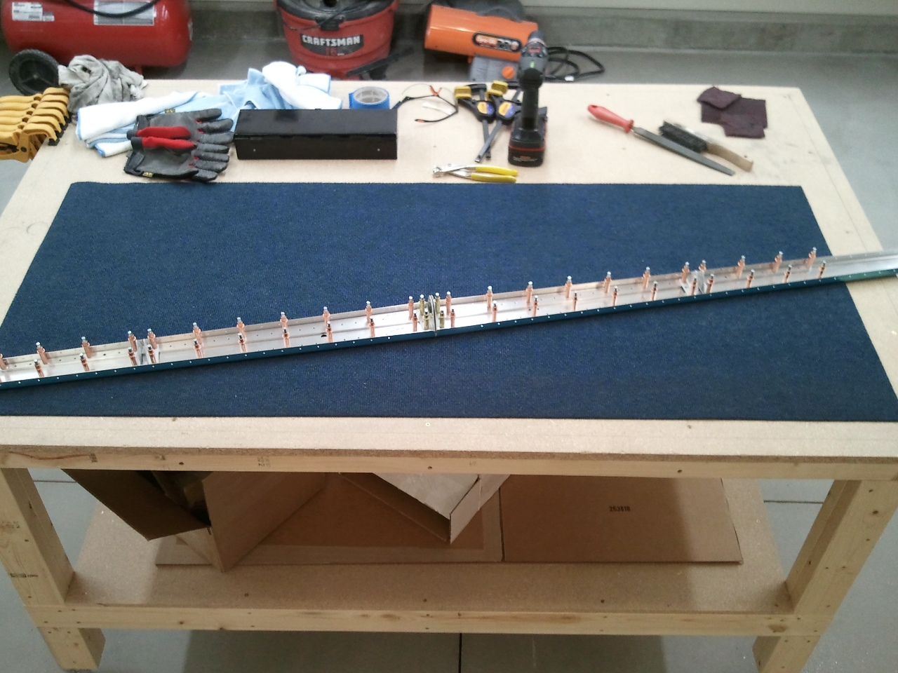
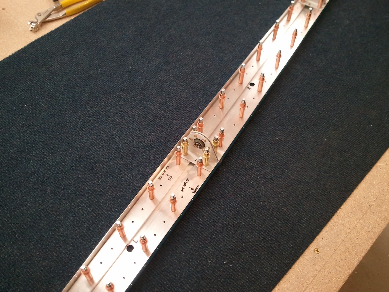
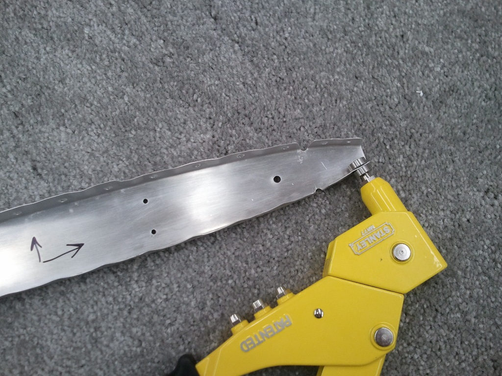
Was able to get all the skeleton dimpled tonight. The last holes at the nose of rib HS406 needed my pop rivet dimple dies. Sure glad I had a set.  I then dressed all the edges, and then double checked all the scuffing.

I need to get my DRDT-2 table rigged up so I can dimple the skins to match the sub structure. Hopefully sometime this week I will get to it. Once that is complete I will prime all the parts and then start final assembly of the HS sub assembly.

Categories: Horizontal Stabilizer

Full Day of Horizontal Stabilizer Work

May 14th, 2011 No comments

The Tricky Drilling

After a good restful sleep, it was time to get some real work done. I mentioned in the previous post, several mistakes have been made in the assembly of the HS by other builders. I did not want to make the same ones and was now willing to take a swing at it.

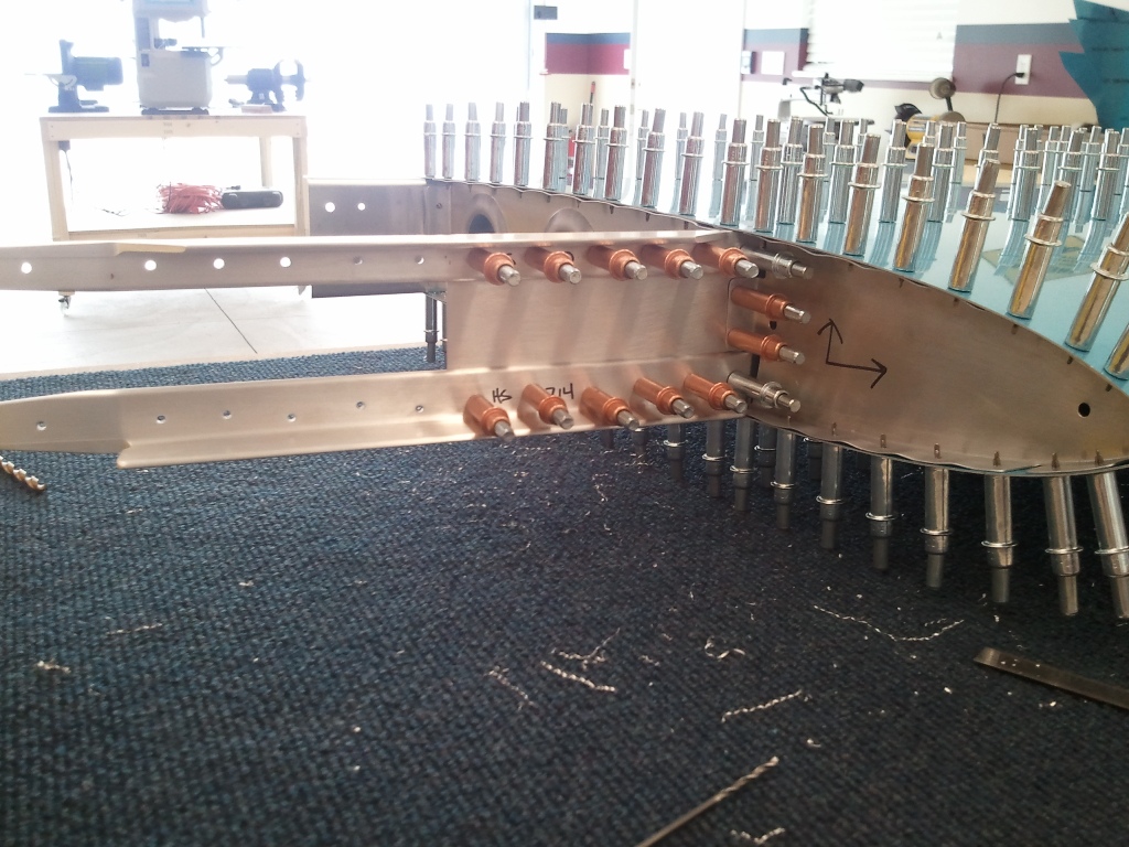
The first area of concern is the flange of the forward HS404 Rib to the HS702 spar connection. Despite my best efforts, I made a similar mistake that others have. The problem stems from needing to drill from the back side of the HS405 rib, through the HS702 spar into, the HS404 flange. You are essentially doing this blind. This left me with the 2 holes in the flange a little closer to the 2x Diameter to the center of the #30 hole distance recommended, but within the MilSpec (MS) required edge distance. The other contributing factor is that when the HS404 rib is installed into the skin opening for it, it causes the rib to concave some and moves the flange inward. The flange could be scabbed and replaced, but I have chosen to build on as it is not a structural connection and it is within the MilSpec.

The second problem with the backside drilling is that some have busted the edge distance of the stiffeners when drilling though the spar and the stiffeners. I was very concerned about this connection as it IS structural for the empennage. I was VERY careful here and pleased to report that on the left side, I was well within the edge distance when drilling these holes. Whew!!!

Left HS Match Drilling Complete!

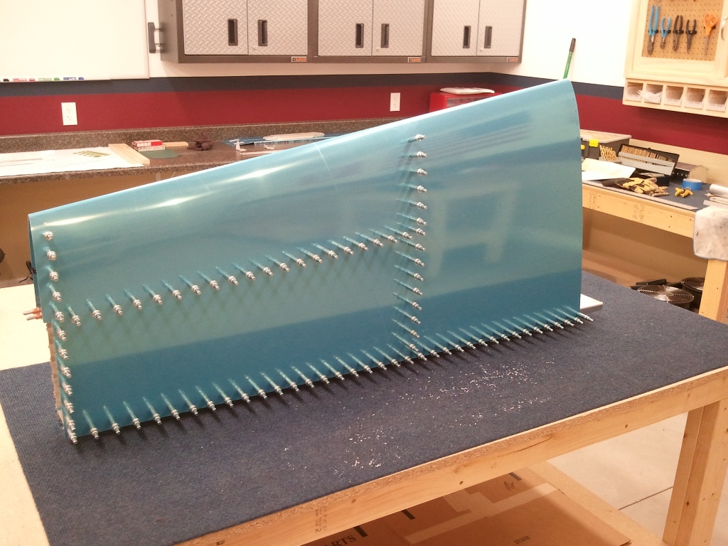
Once the HS404 and HS405 ribs are match drilled to the skin, you then completely match drill ALL the holes in the skin to the sub structure. My hand got sore undoing and redoing all those clecos. Remember, they are on both sides of the HS in this picture. I love how precise all the punched holes are in all the parts Vans supplies. Made lining up everything a real dream. In older kits, you had to lay out the rivet holes in the skin and then drill them all then match drill them to the sub structure. I am glad I don’t.
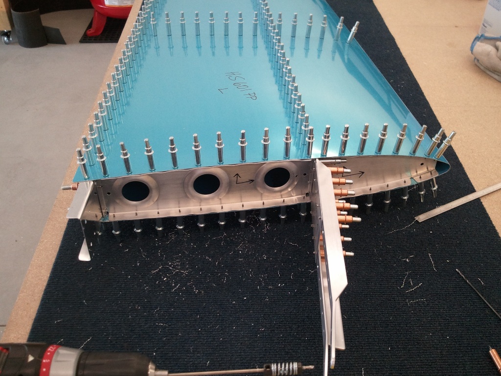
Left HS Ready to be Disassembled

The above shot is of the Left HS complete and ready to be disassembled. Wait…I jut got it all together and looking cool. What do you mean I have to take apart. Welcome to building a plane. I took out all those clecos, and set the parts aside. Then next step is to dimple all the holes and the corresponding holes in the sub structure to accept the flush AD3 rivets. Then I will prime and begin to reassemble for the final time. The real riveting will begin soon enough.

With the left side complete, it is time to repeat all the steps just completed for the right side. With the hard stuff figured out, and experience now fresh…this will go like a breeze right? WRONG!

Remember back in the HS405′s Prepped and Drilled post when I noted that forward flanges were not located symmetrically? Well it came back to bite me. I was able to successfully drill the HS404 to HS702 flange connection correct this time, but when it came to the stiffeners….well, I thought, heck it worked on the other side just right…it will work here fine too. Long story short, when drilling through the HS405 through HS702 through HS710 hole, I looked and was horrified to see that the hole looked to have busted the 2x Diameter edge distance. After a few thumps to my head in frustration, I measured the hole. I am at 0.250″ from the center of the hole to the edge! That 1/4″ looks way smaller when you are scared. Crisis averted.

New Builders beware of the HS405 webs….they are not created equal and must be the cause of this common mistake. The forward flange IS NOT CENTERED on the rib. You will get different height holes on the HS710 and HS714’s no matter what you do!
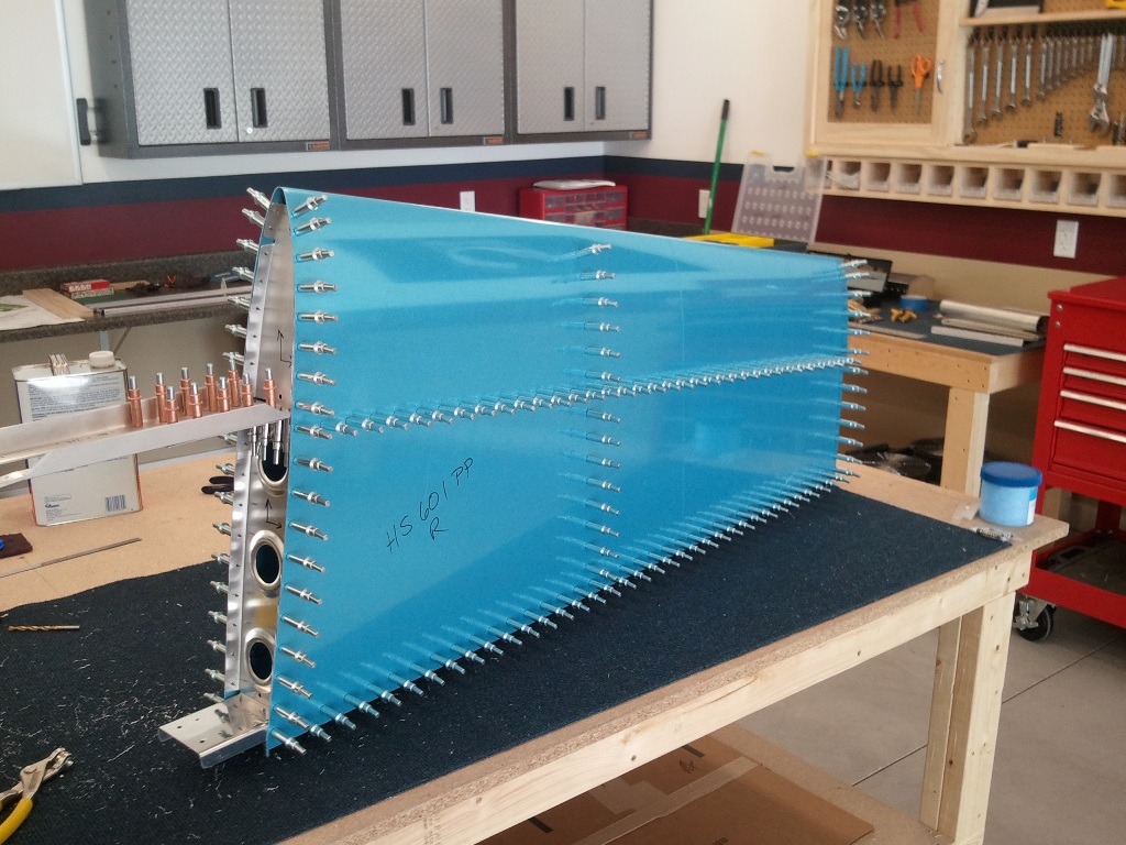
Right HS Completely Matched Drilled and Ready to be Disassembled

Once I recovered from what I thought would be a costly mistake, I pressed on and match drilled the right HS Skin to the skeleton. If I had enough clecos, I could have made a full HS looking structure temporarily. Alas…in time, I will do it permanently.
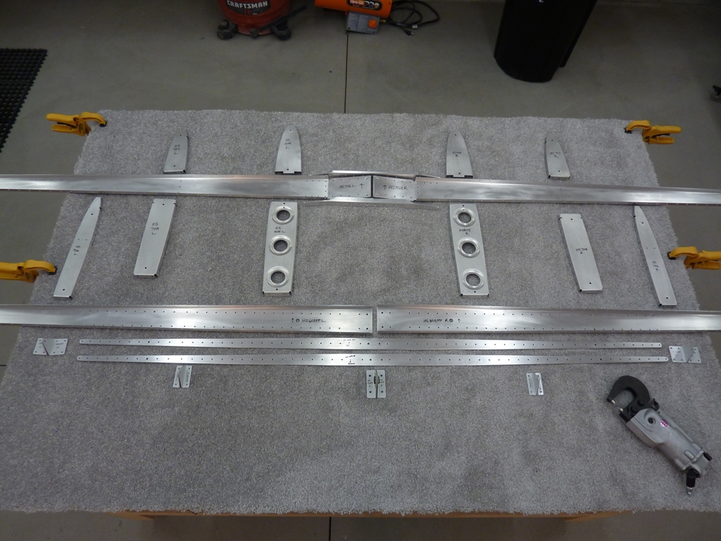
The HS Skeleton Overview Shot

The last thing to get accomplished today was to clean all the skeleton parts, lightly scuff them, and then mark the part numbers and locations on them. I will dimple the parts sometime this week and then clean once more and then prime them. Additionally, I will use my DRDT-2 to dimple the skins and then prime the inside of them. Then the fun of riveting will begin. THAT was a good day of real progress.

Categories: Horizontal Stabilizer

HS Skins in Works

May 13th, 2011 No comments

Left Skin Fit to Sub Structure

Now that the sub structure/skeleton is completely prepped/drilled, it is time to cleco on the skins and match drill them together. Here is the start of the left HS skin. Once this is on, you have to complete the drilling and fluting of the inboard ribs that surround the fore spar. Then you match drill them to the skin, the spar, and the stiffeners. Here is where I have seen several make some mistakes that are costly.

Another View of the Skin Attached and the Inboard Ribs Slipped In

It is starting to look like I am building a plane. I called it good for the night. It was late and I needed to take a break and snuggle with my lovely wife.

Categories: Horizontal Stabilizer

Ribs Nearly Ready For Assembly

May 11th, 2011 No comments
Ribs Fluted and Deburred and Nearly All Cleaned

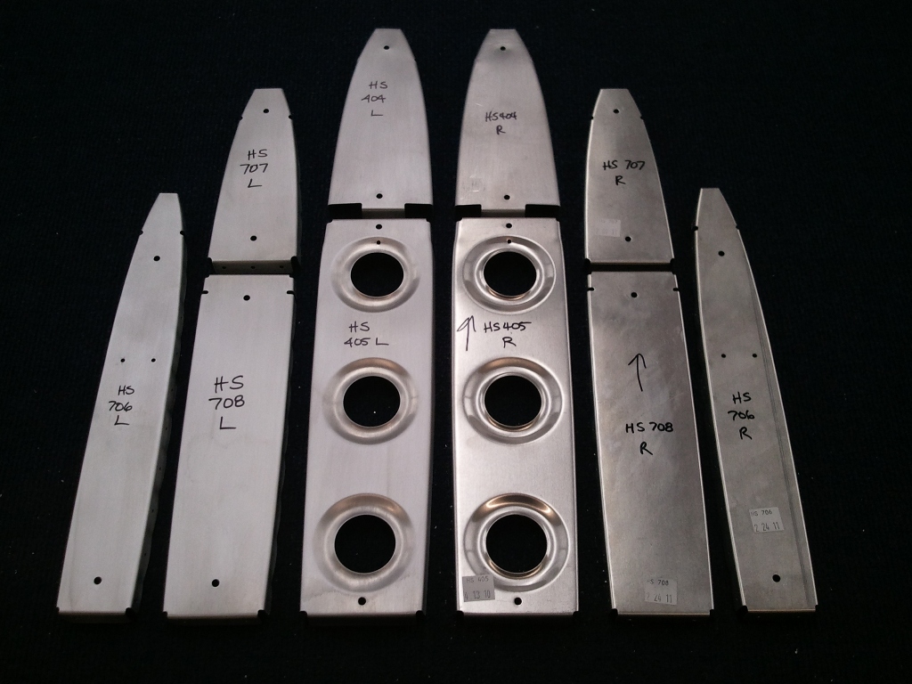
Here is a shot of the HS ribs marked, separated into Left and Right sets, and half are cleaned and deburred. I fluted using my fluting pliers and they all came out straight. A little more cleaning and they will be ready for assembly into the skins for match drilling and beyond. I am almost to the point where it will look like I am starting to build a plane.

Categories: Horizontal Stabilizer

HS405’s Prepped and Drilled

May 11th, 2011 No comments

One Side Drilled, One to Go

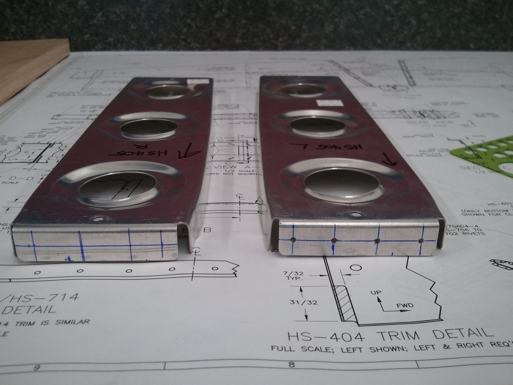
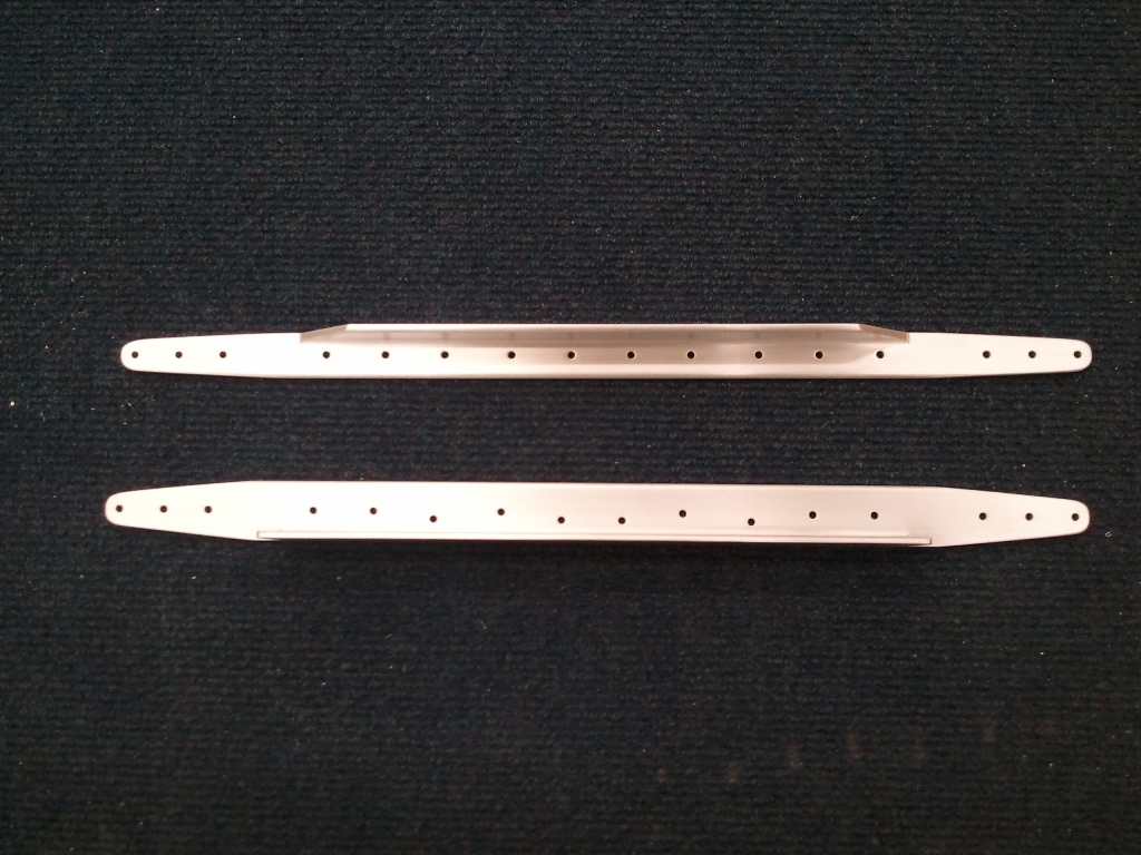
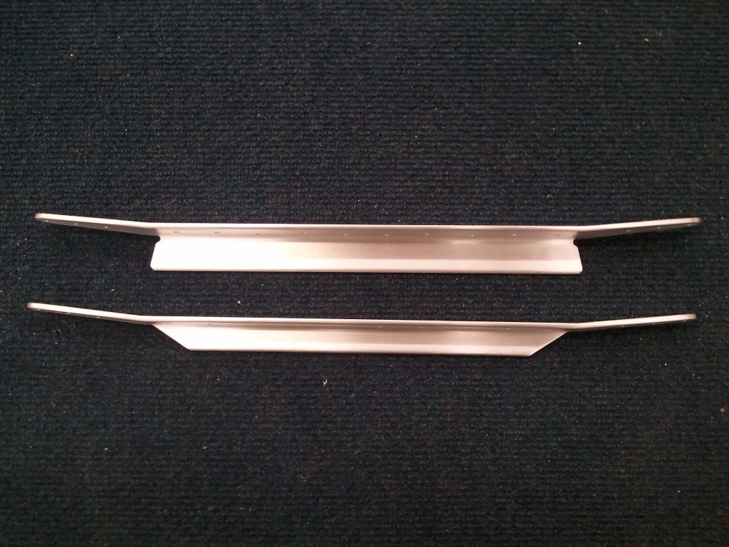
After the HS404’s are notched, the next step is to mark and drill the forward flange of the HS405 ribs. These are located between the forward spar and the rear spar of the HS. The tricky part is making sure that the holes you mark and drill here provide adequate edge distance to not only the flange you are drilling, but the flange of the HS404 tab that was left after notching it, and the stiffeners on the forward spar. I followed the plans to the “T” and still measured 15 times.

I noticed that while the ribs are symmetrical top to bottom, the bends for the skin flanges are not. This means the forward tab is higher than the other if you place these back to back. So, as you can see, the marks on the tabs above are not exactly a mirror of each other. They are offset by the differential in the bends for the flanges being different.

That being said, I was able to mark and drill so that it met all the required distances and compensate for the offset of the tab just fine. This will ring true when they are matched drilled to the spar and stiffeners and the leading edge ribs (HS404’s).

I also learned the value of a good center punch. Makes locating accurate holes a breeze.

Categories: Horizontal Stabilizer

HS404’s Notched

May 11th, 2011 No comments

HS404’s marked per plans

One of the next steps after getting the Fore HS Spar prepped is notching the inboard leading edge ribs for the HS notched to go around the stiffeners prepped in earlier steps.

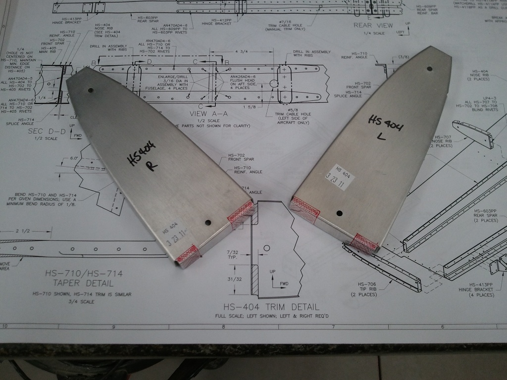
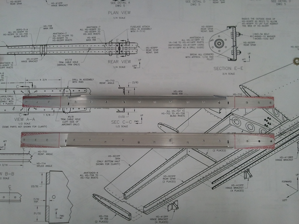
Here you can see the full size detail on the plans and the ribs with the areas that need removing marked in red. I first drilled the corners with a #30 bit and then rough cut the edges close to the limits with my band saw. Then I cleaned up the edges of the cut with a fine file until they were blended with the holes in the corners.

Here is the result:

HS404’s after Notched Per Plans

They are spot on with the plans and ready to be drilled to the spar. The trick is…TAKE YOUR TIME and file as little as needed. I am learning patience in these early build steps. I think that will be the more valuable lesson as the build progresses.

Categories: Horizontal Stabilizer

Spars Ready for Ribs

May 7th, 2011 No comments
Fore and Aft Spars Together

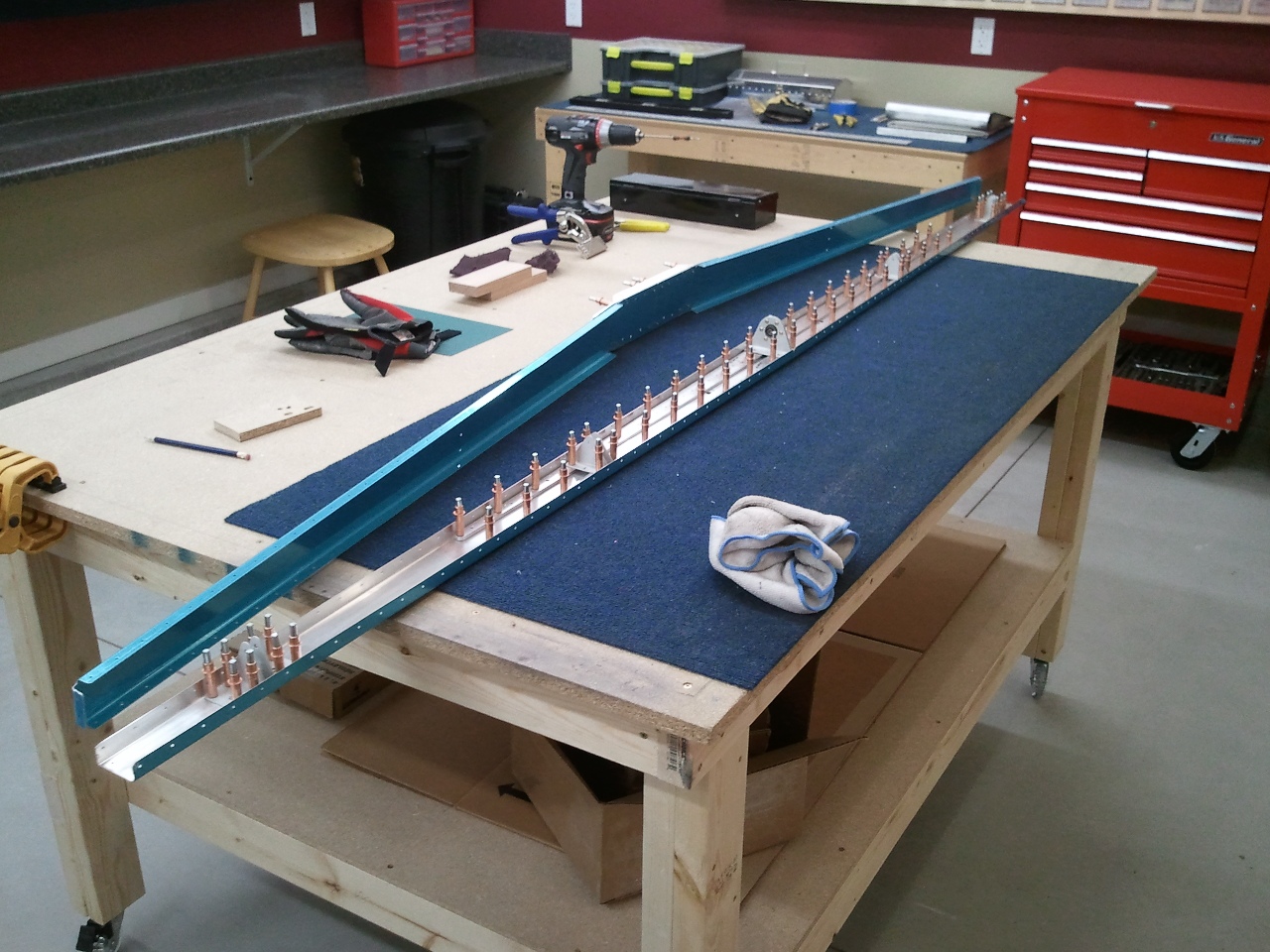
Here are the two spars of the Horizontal Stabilizer together on the bench. Almost time to get the ribs started and get these two assemblies joined.

Categories: Horizontal Stabilizer

Forward Horizontal Stabilizer Spars in Works

May 6th, 2011 No comments

Fore Spar Stiffeners Marked for Trimming

Here are the fore horizontal stabilizer stiffeners marked and ready for trimming. I learned that the last holes on the ends are right at the required edge distance. DO NOT take any material other than the milling marks off the ends when radiusing. If you do, you may not make your edge distance specs.

Trimmed and Polished and Ready to be Bent

I completed the trims and then had to make the 6° bends to the tails for the fore spars to make the tapered shape.

The 6° "Bends" Completed

I also completed the bend relief holes in the fore spars and the corresponding 6° bends in them to match the stiffeners. Next is the dimpling of the spars and the countersinking of the stiffeners for the four inner rivet holes.

Categories: Horizontal Stabilizer

Horizontal Spar Assembly Complete

April 27th, 2011 No comments

Spar Assembly complete

HS Spar is complete and ready for primer. All holes are deburred and edges are dressed. At this point, the parts are set aside and now on to the Forward Spar assembly.

Categories: Horizontal Stabilizer

Bearing installed

April 27th, 2011 No comments

Bearing Assembly Matched Drilled

Once the bearing assembly is riveted, you match drill it to the spar. I sighted down the spar through all the hinge pivot points. It is straight as an arrow, right down the middle of the holes. This kit is a thing of beauty.

Categories: Horizontal Stabilizer

First Rivets Set

April 27th, 2011 No comments

First Rivets of my plane are now set

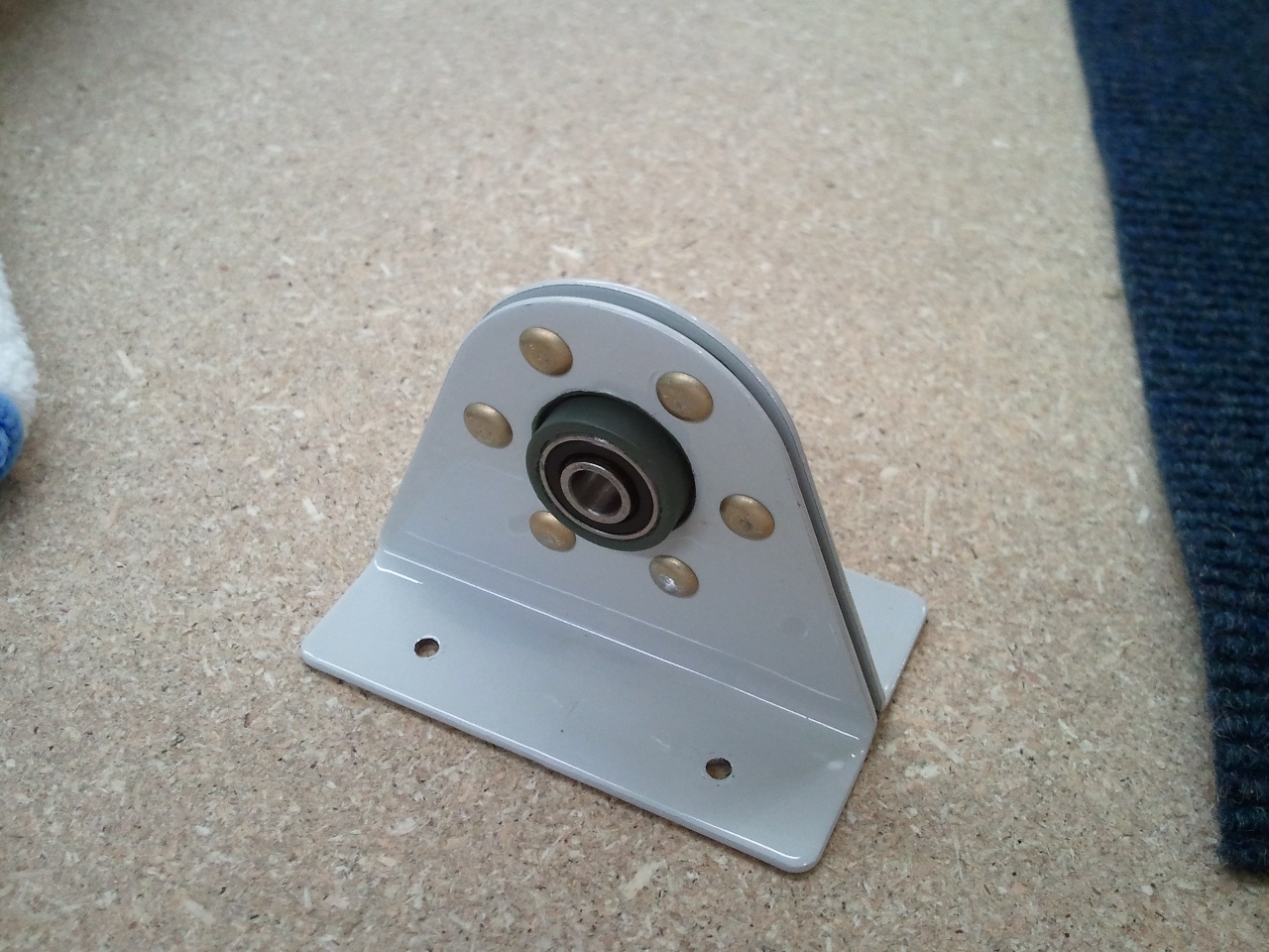
So…here is the completed elevator bearing assembly. The first 6 rivets are now in the books. I am using a pneumatic squeezer. Worth every penny. Consistent, clean, and correct.

Categories: Horizontal Stabilizer

Elevator Bearing Primed

April 27th, 2011 No comments

Prepped and Primed

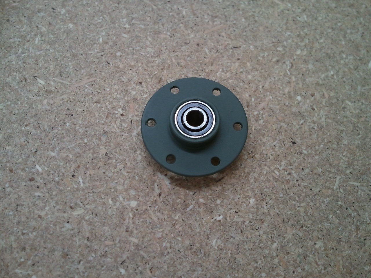
After all the rear spar stiffeners and channels were match drilled, I prepped and primed the elevator bearing. I am using Dupli-Color’s self etching. I like how it sprays and heck, I even like the color. The next step is to rivet it to its brackets.

Categories: Horizontal Stabilizer

Horizontal Stabilizer In Works

April 23rd, 2011 No comments

The matched punched assemblies are spot on

Every RV starts here. I had to debur the Spar Stiffeners and round over the edges near the channel bends a bit for a flush mating. Then the ends were rounded over to remove the points (aka crack generators). Once both were buffed to a smooth satin finish, I clecod the rear spar and the stiffeners together. Next step is to match drill them.


Categories: Horizontal Stabilizer