Leading edge riveting complete
Saturdays are always a good day in the shop. Both therapeutic and productive. I set out with the goal of knocking out a ton of work. Started the morning by riveting all the ribs to the skin. I actually enjoyed the solo riveting. Only had to drill out two. The swivel head flush set and tungsten bucking bar make setting AD3’s a breeze. You do have to be very careful not to drop the tungsten bar, is it will dent anything it hits with very little effort. Lay a foam pad or something thick and soft below where you are riveting just in case. I fortunately had no drops…but I have heard of others not being as lucky.
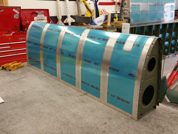
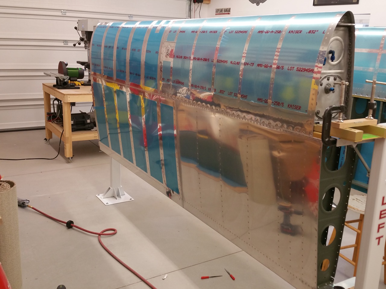
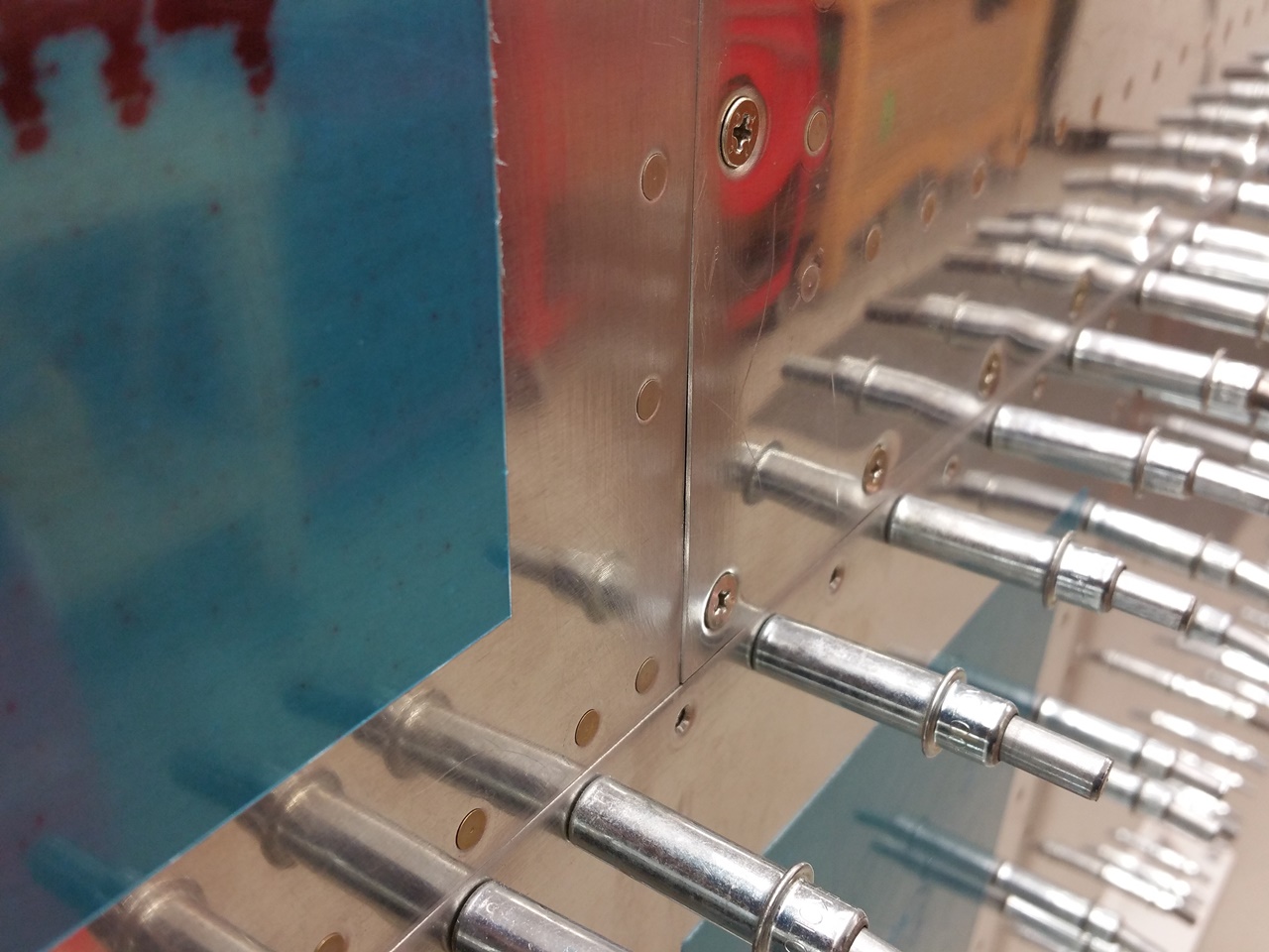
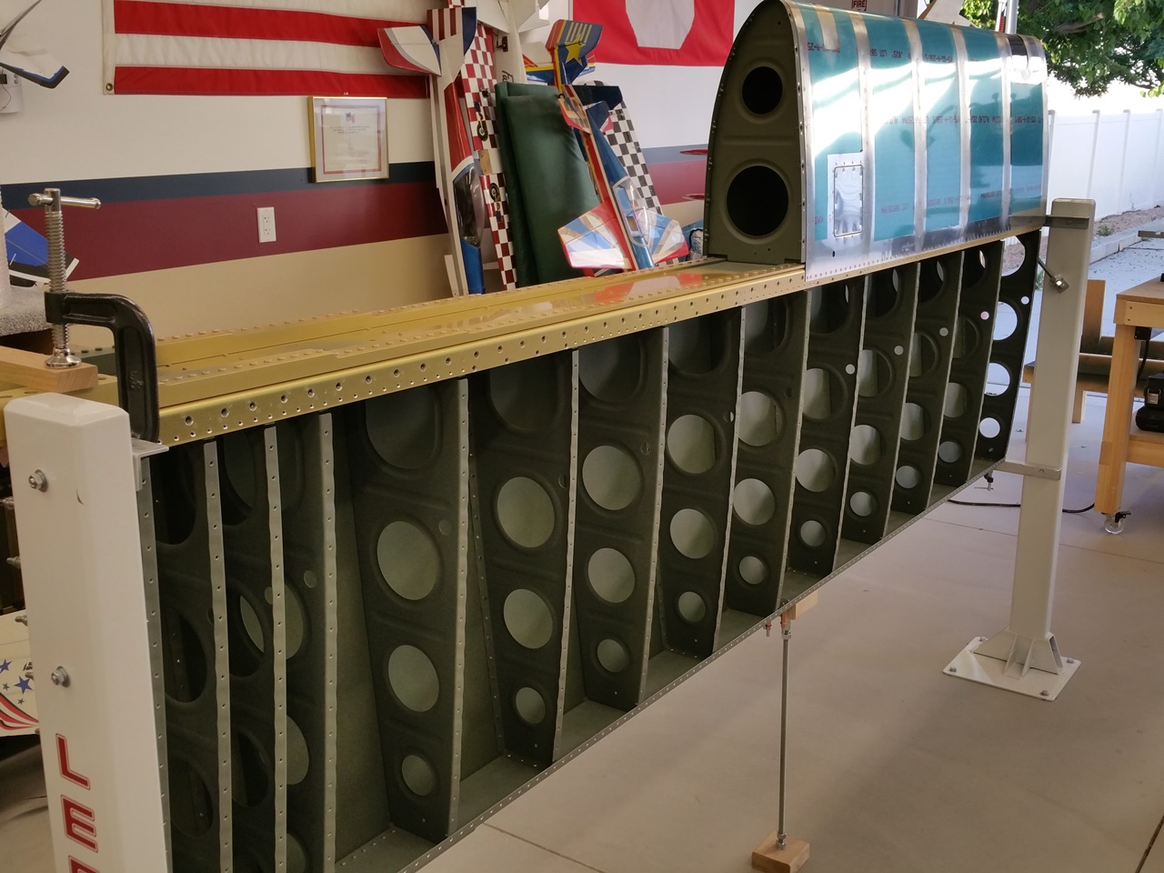
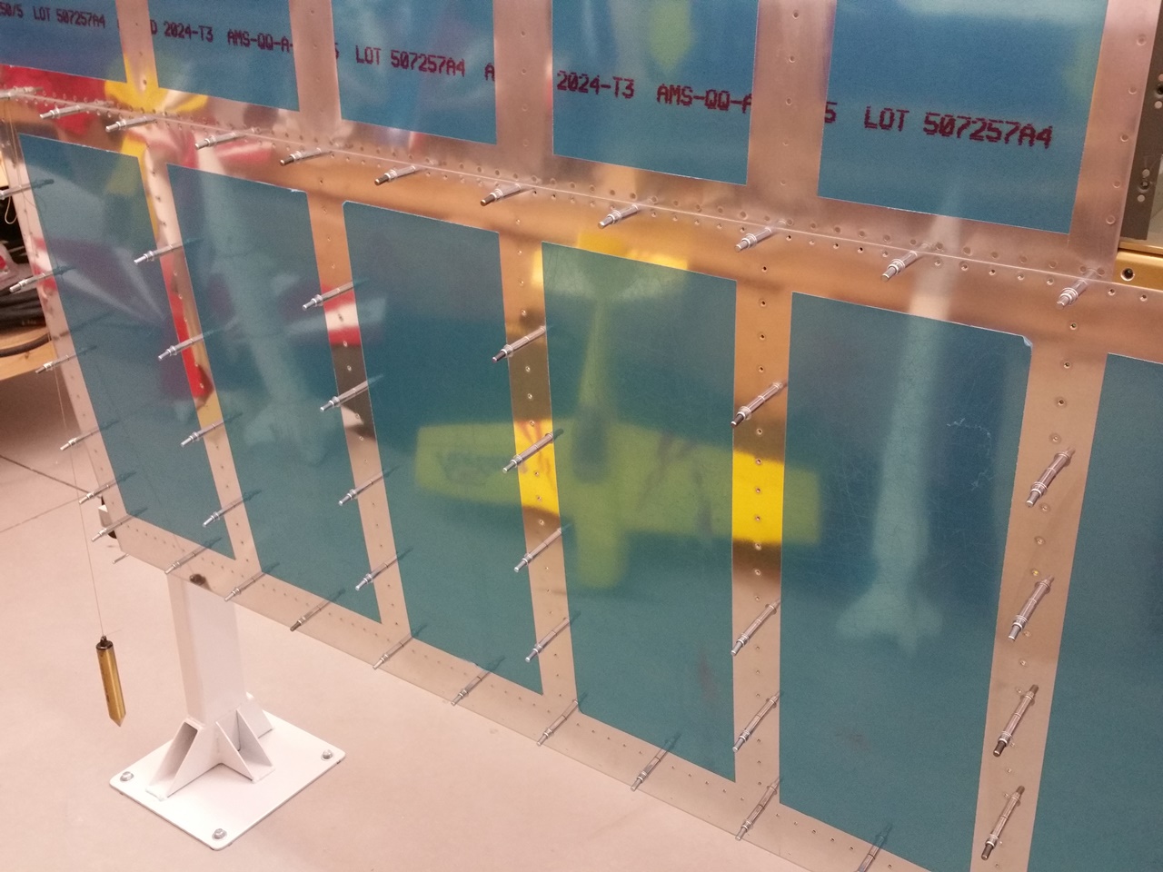
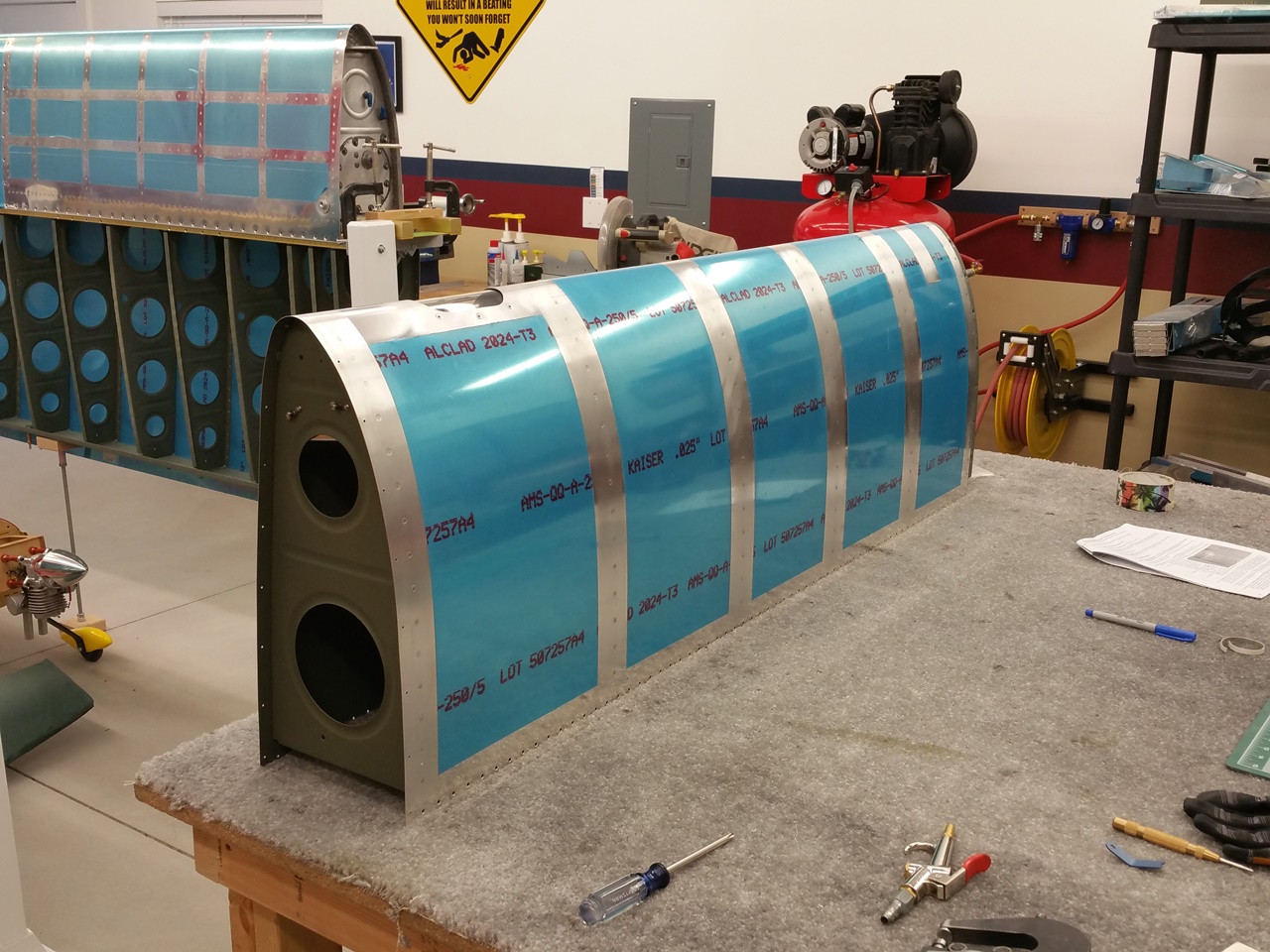
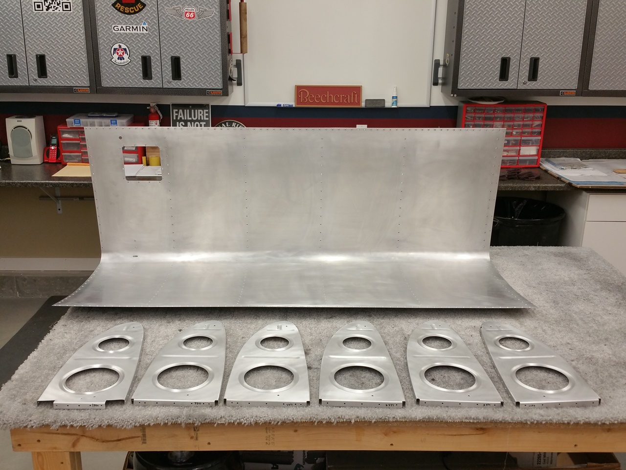
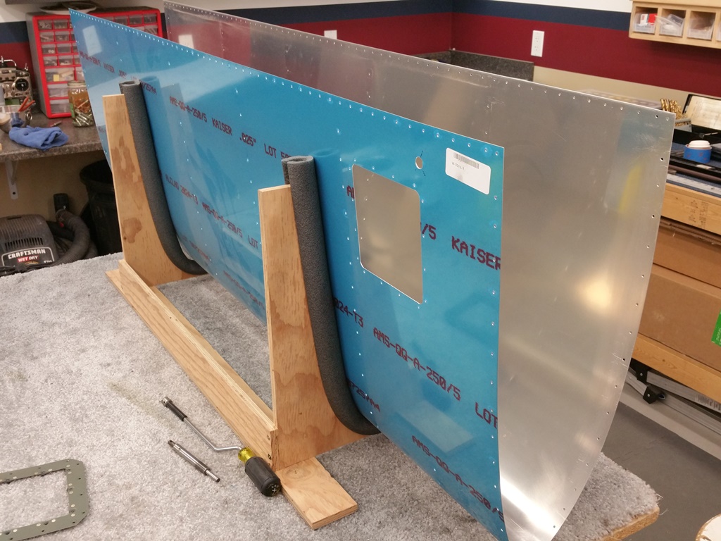
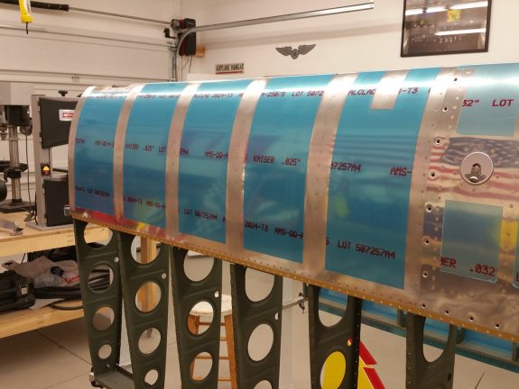
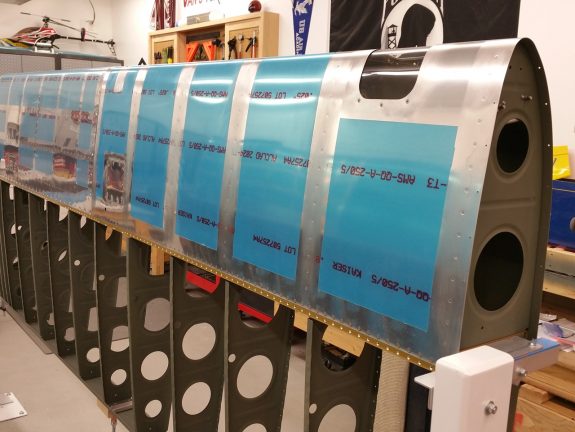
Left leading edge riveted
Here is a good shot of the leading edge out of the cradle post completing the ribs. I’ve heard others say that the Wings are fun because you really get the sense of building something big as you complete sections. I agree.
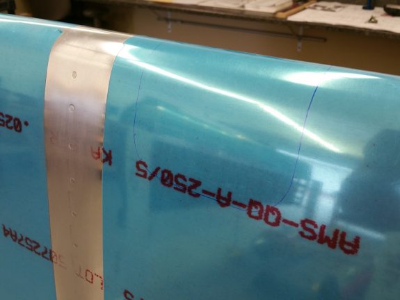
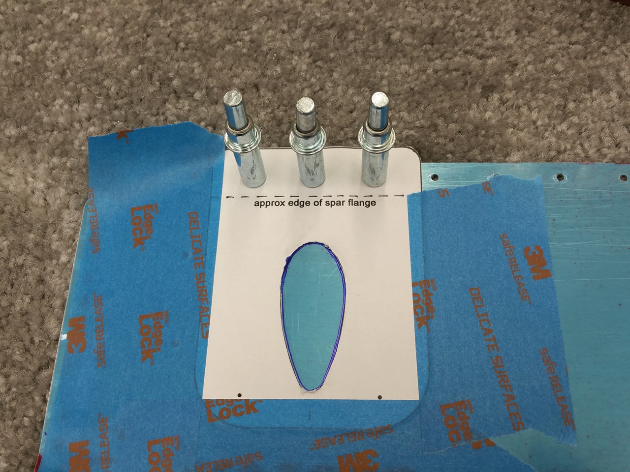
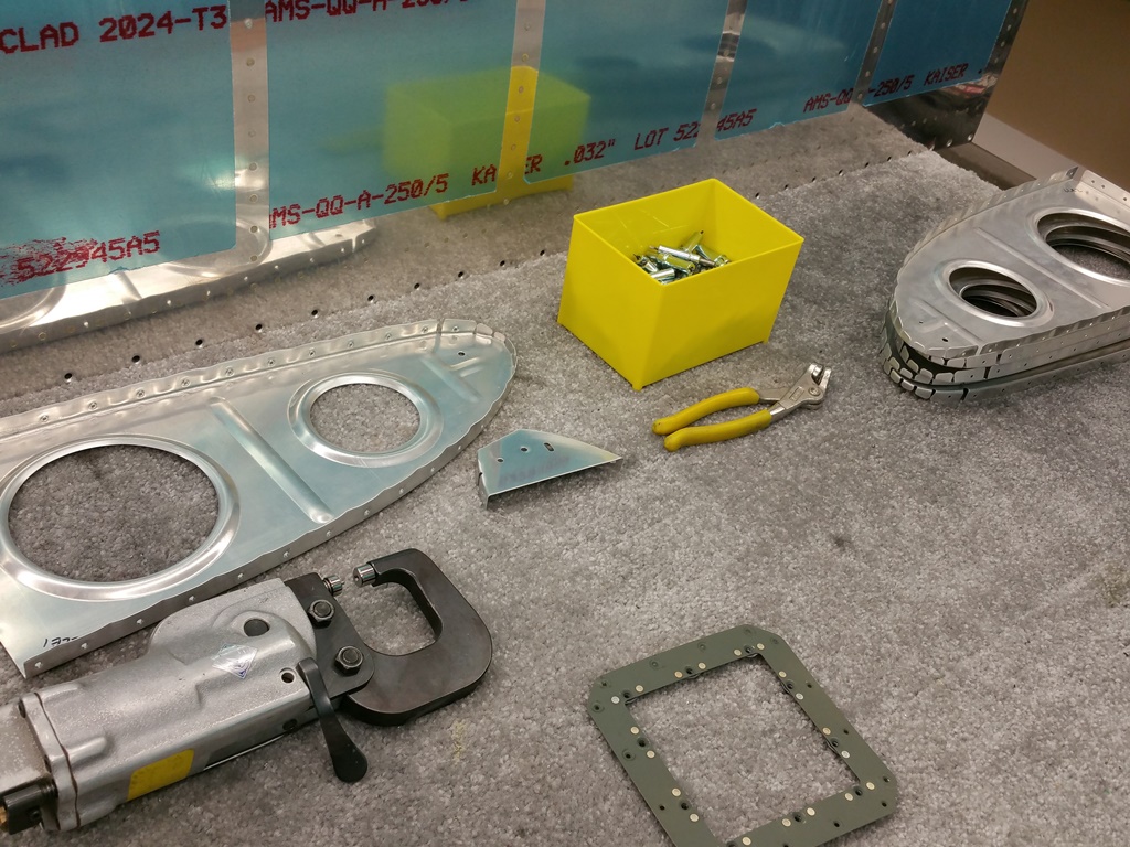
Marking the left leading edge for scary cut out
Once all the riveting was done, I quickly set out to cut a big hole in it. I was surprised how much mental effort it took to convince myself to start drilling and cutting. After all, I had just completed the assembly to near perfection in my mind. No matter, I committed.
I first marked locations to use my step bit and get 3/4″ to 1″ holes near the corners. From there I used a Dremmel and a cut off wheel to connect the holes as close to the template line as possible. From there it was simply a matter of filing to final shape. Take your time here and be patient. Once the hole was done to my satisfaction, I moved to marking, drilling, and dimpling the holes for the lens screws per the template.
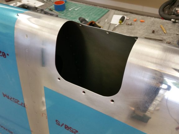
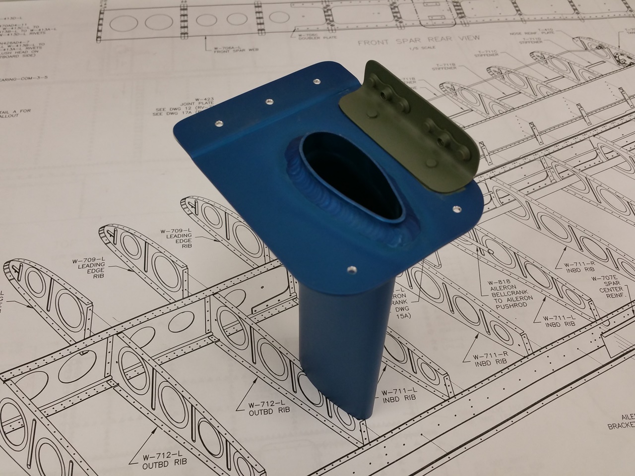
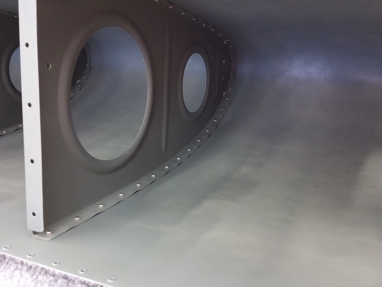
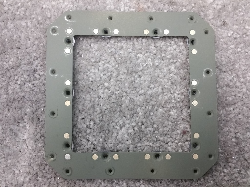
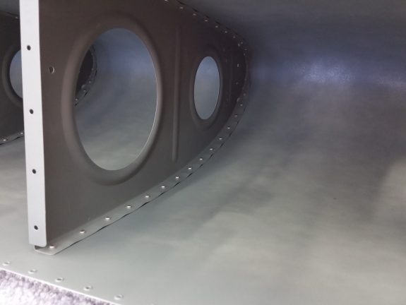
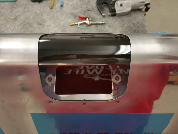
Left Duckworks cutout
Here you see the cutout complete and ready to accept the Plexi lens.
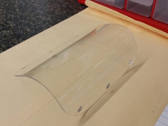
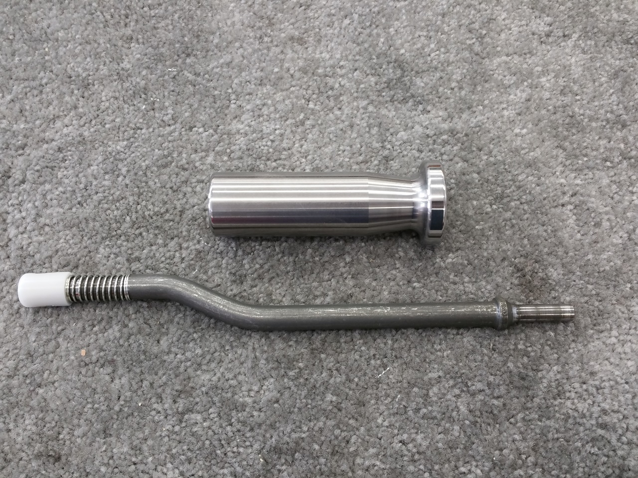
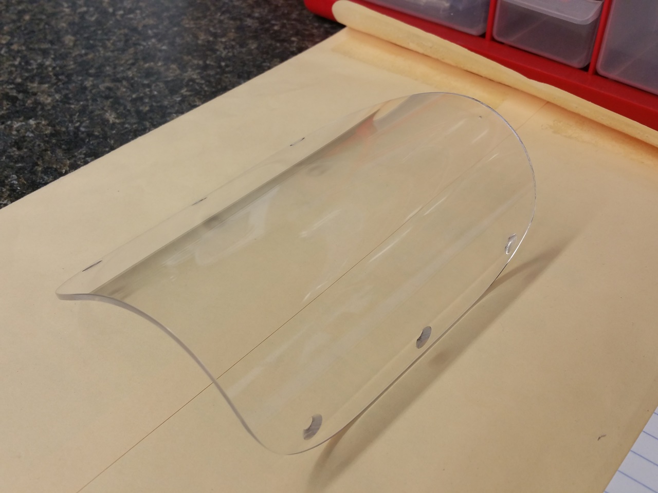
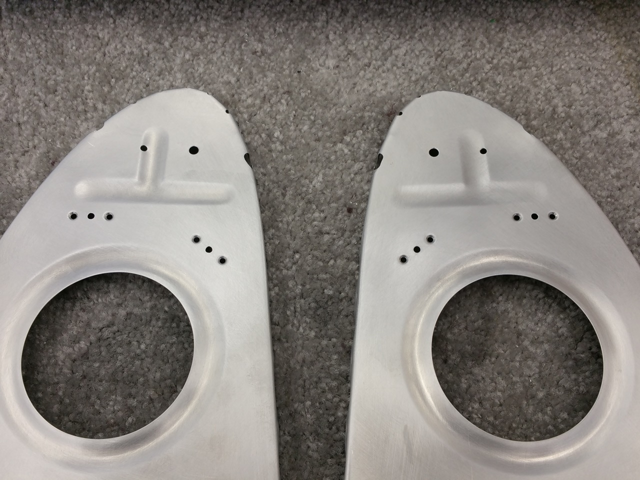
Duckworks lens cut, trimmed, polished, and countersunk
The Duckworks lens is a bit of fun, work, and scare. Unless you have worked with Plexiglas before, it can bite you fast. Fortunately, I did a bit of Plexiglas work in High School years ago, and I remembered how finicky it can be. First, take your time. Remove ALL nicks and burrs on the edges. Drill very slow and polish the edges to a near clear appearance. Make sure you mask the edge before you polish…or you will ruin the field of the lens in a heartbeat. All holes must be deburred or you will crack it.
The above shows the lens after all the work to trim the raw (but properly molded leading edge shape).
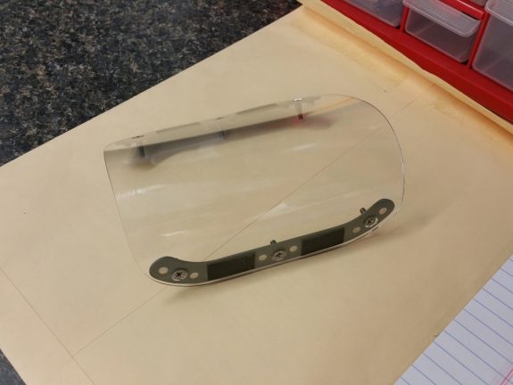
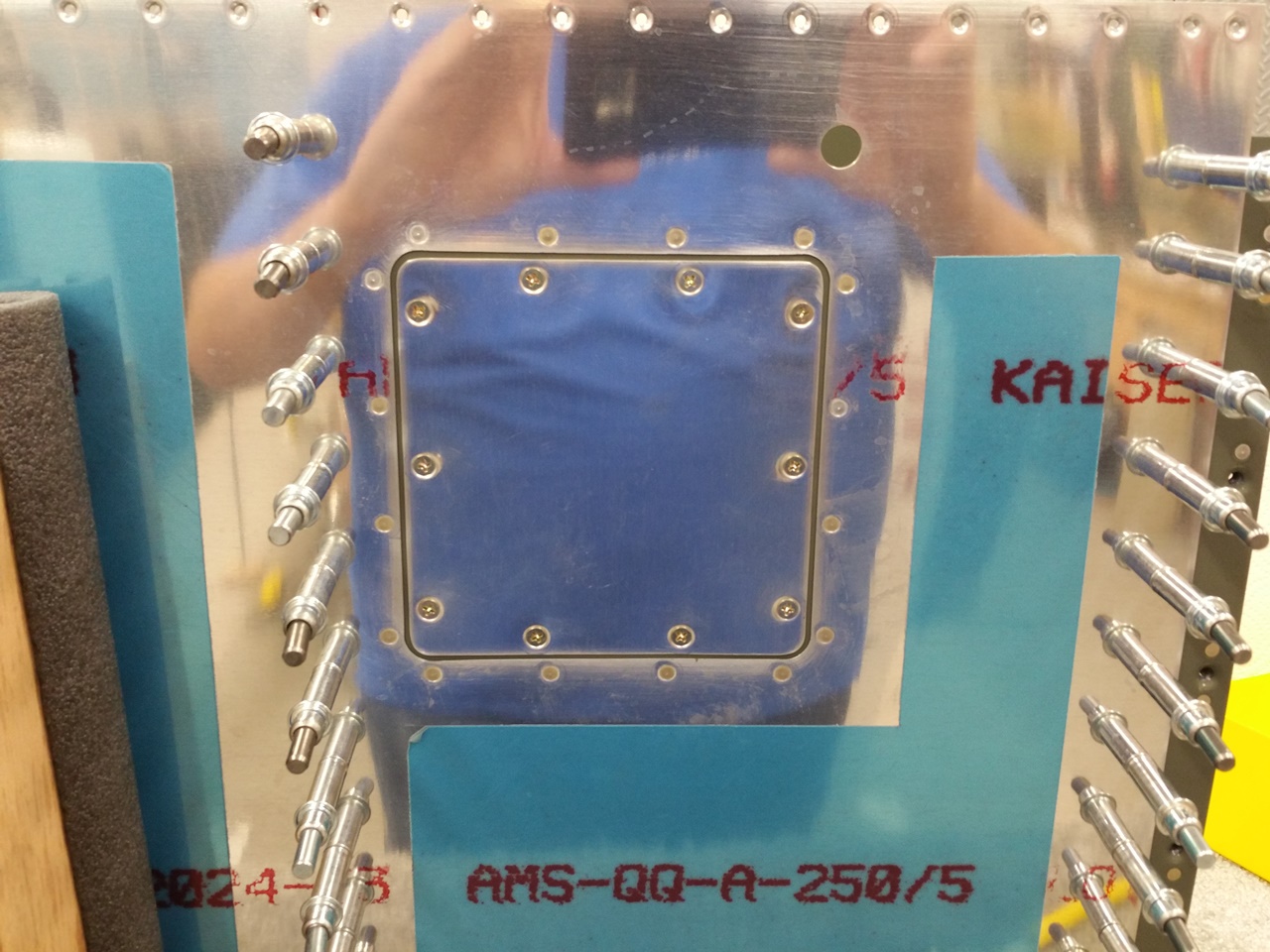
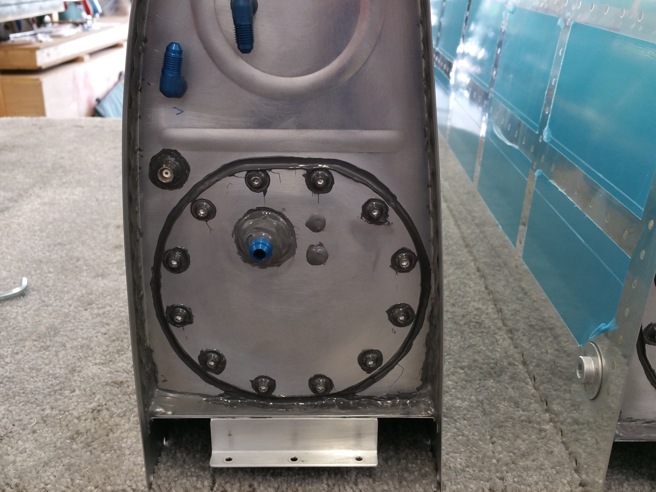
Duckworks lens assembly complete
Here is the lens after attaching the doublers with platenuts.

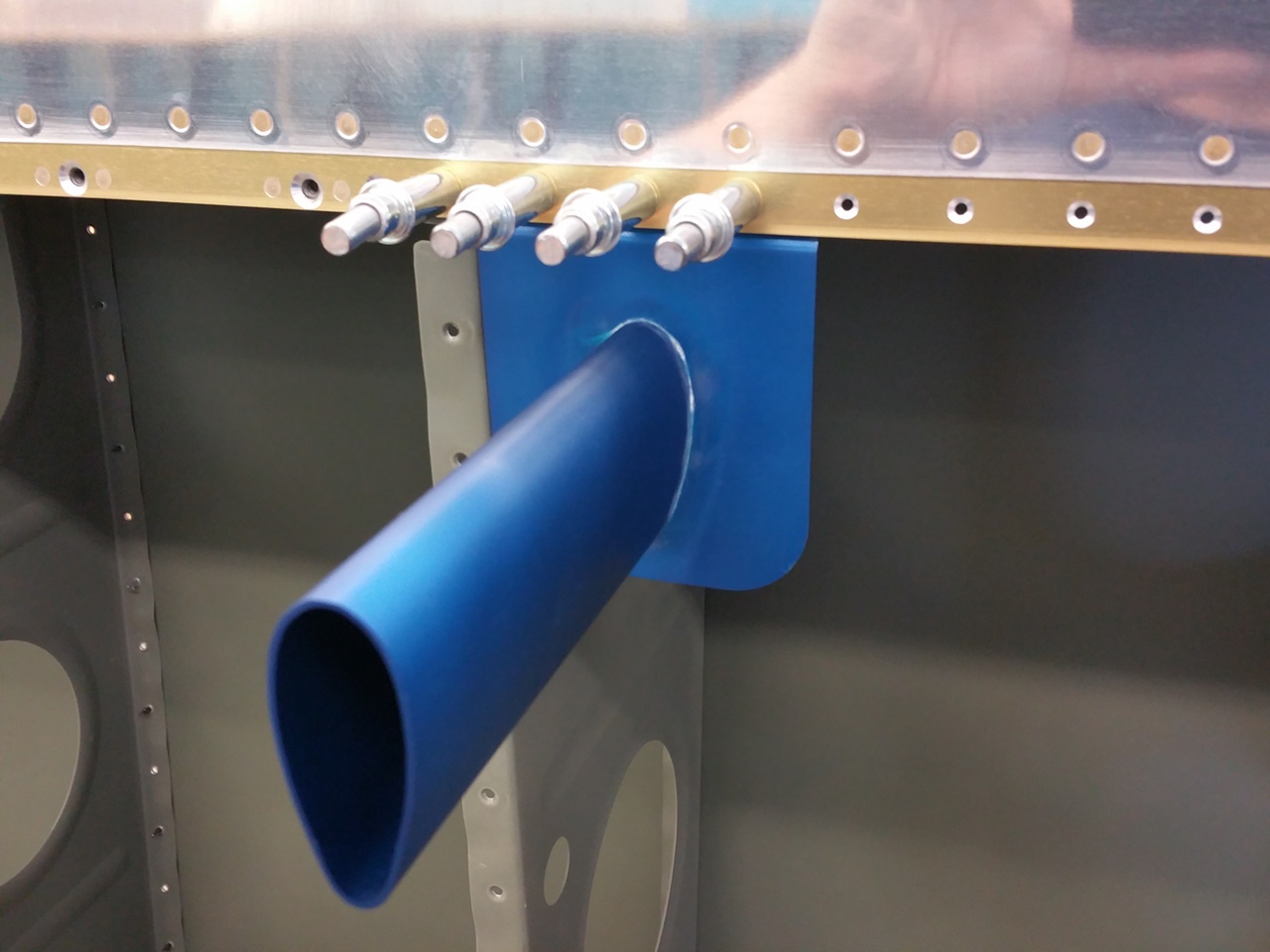
Duckworks light kit – bottom view
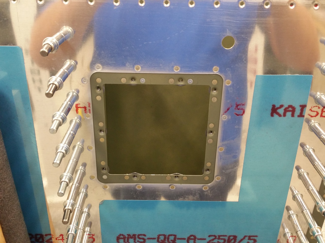
After all the Duckworks kit work, it was time to see if the lens fit. It appears to fit nicely and as tight as one can get it with the gasket they provide.
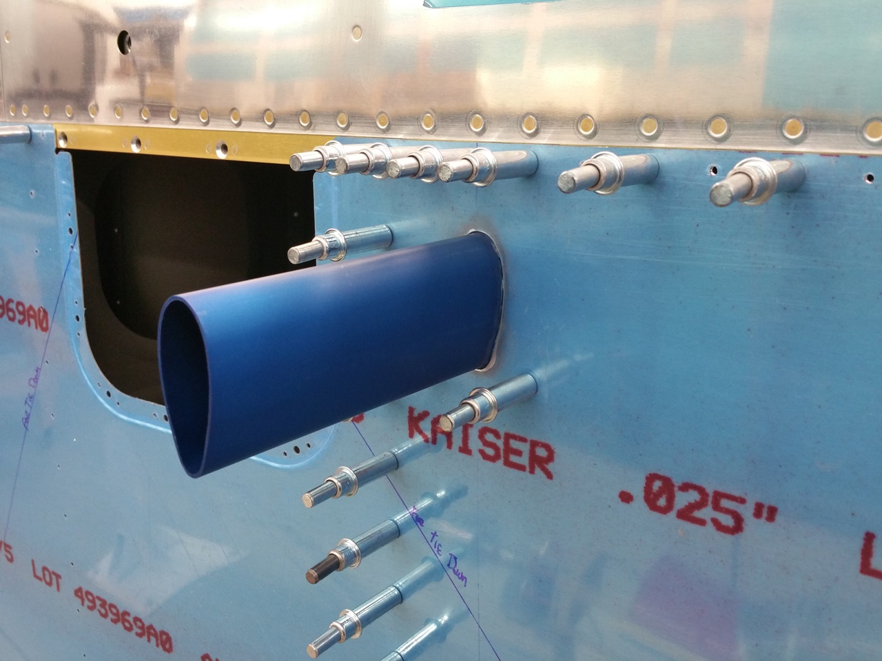
Duckworks light kit – top view
Duckworks lens and light holder

Left leading edge after Duckworks light kit was completed
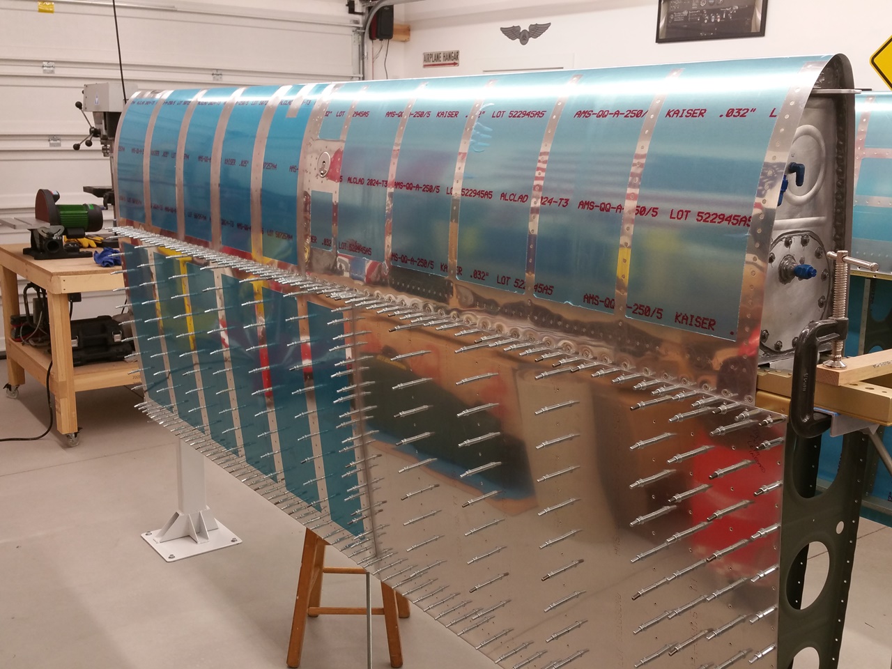
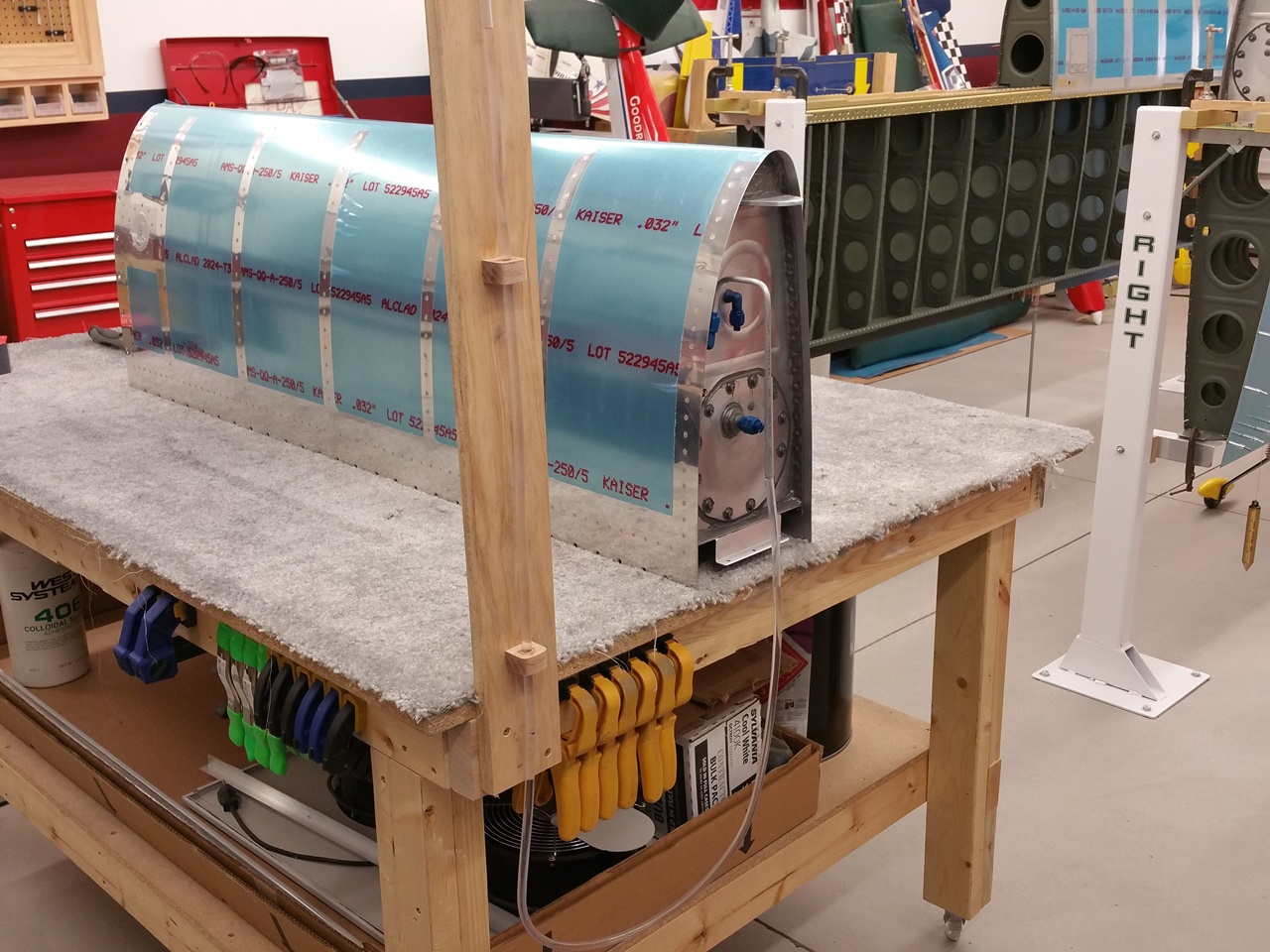
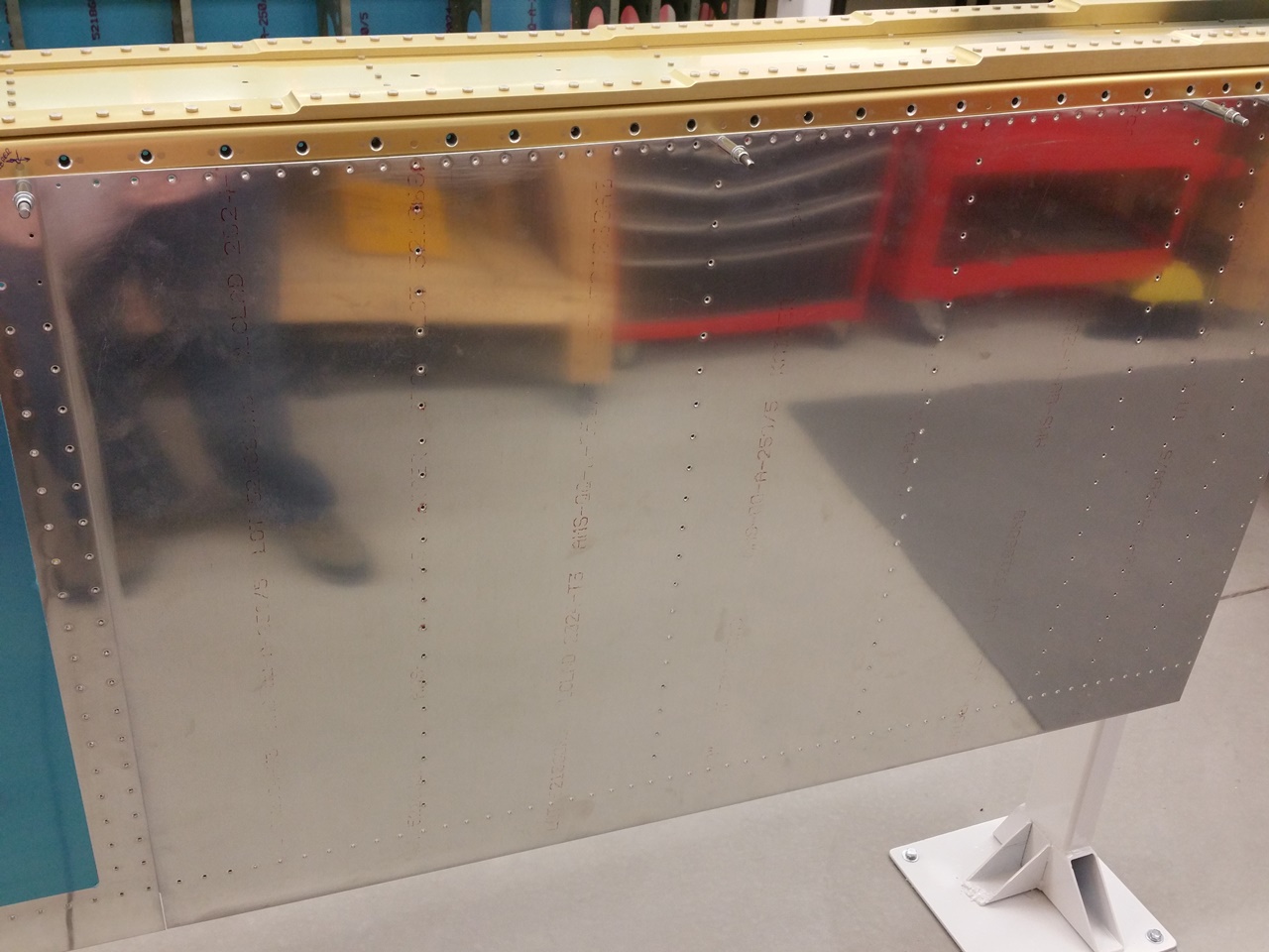
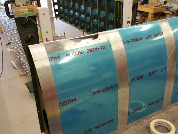
Left leading edge riveted to spar – top view
Since I was clipping along for the day, I figured I’d test fit the leading edge to the spar. Looked good, so I set out to rivet it on with the pneumatic squeezer. This made quick work of both the top and bottom rows.
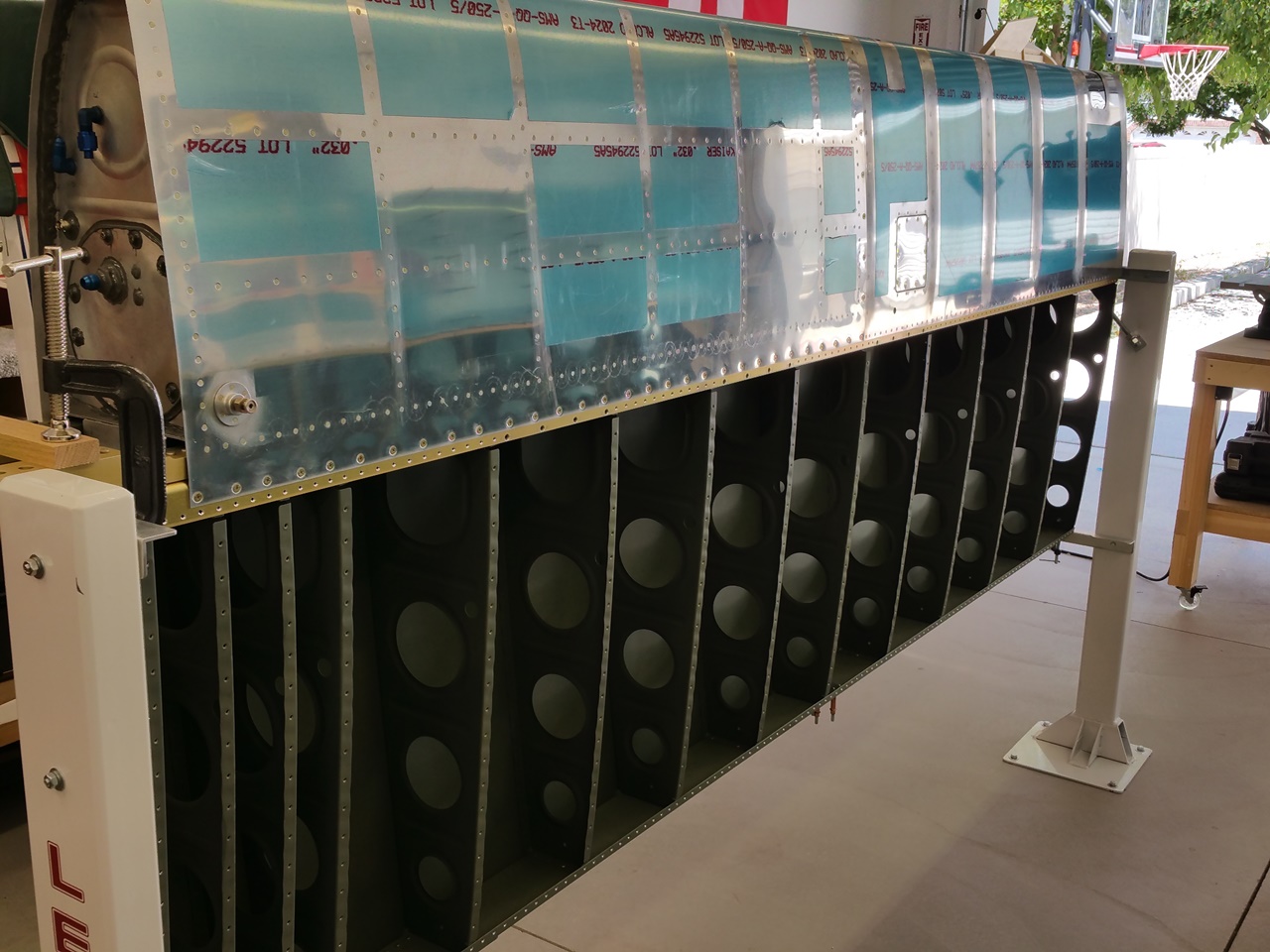
Left leading edge riveted to spar – bottom view
What a great sight. No clecos on the entire leading edge of one wing.

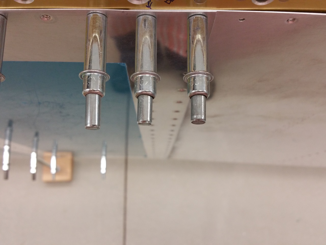
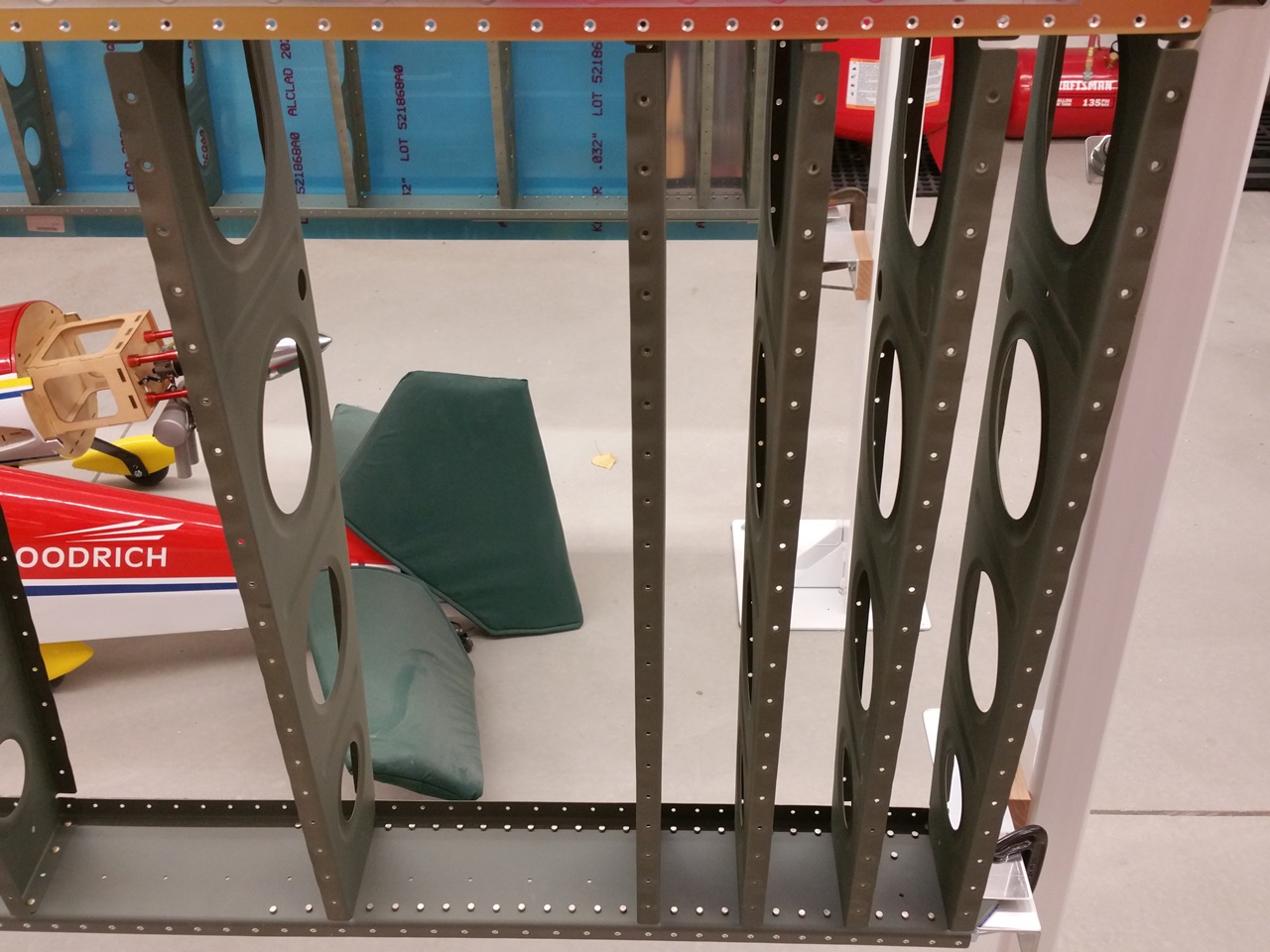
That’s a lot of dimples
I was getting late, but I wanted to get a couple more items done if I could. So I set out to dimple the entire substructure of the left wing. I cannot imagine what my neighbors thought was going on at 2200 hours each time that squeezer slapped those dies crisply together. Rang like a bell. Fortunately, the shop is well insulated, so hopefully, they didn’t even know. After an hour of that however, all I heard was a distinctive “Thwang” ringing.
Once dimpled, I went to do as the instructions said and cleaned out the rear spar holes with a couple of light turns with a deburring bit. This insures that the skin dimples will sit nicely in them. I think it helps solve the “ski-jump” problem that I’ve read about on VAF, as well as compensate for the fact you are dimpling a much thicker piece of metal.
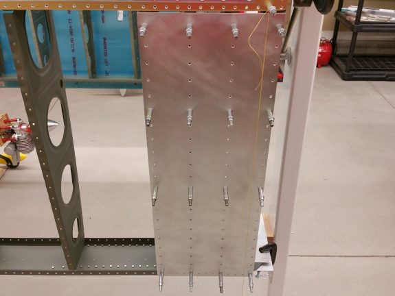
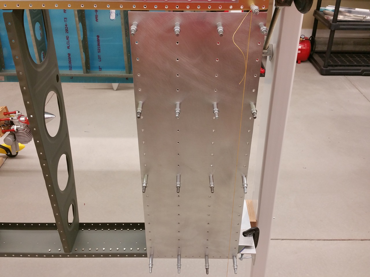
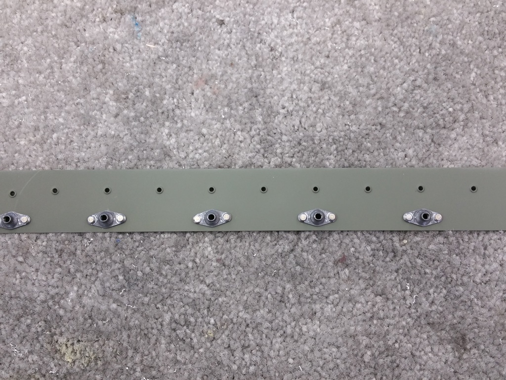
Left wing walk doubler dimpled
Ever get in a groove and just want to keep going? It was 2330 and I was in one. So I dimpled the wing walk doubler, prepped it for primer, then mounted it. Fit like a glove.
Today was a good 16+ hour day in the shop. At this point it was time to call it good for the week.