Archive

Archive for October, 2012

Placarded Wing Stands

October 24th, 2012 No comments

Just to be Clear

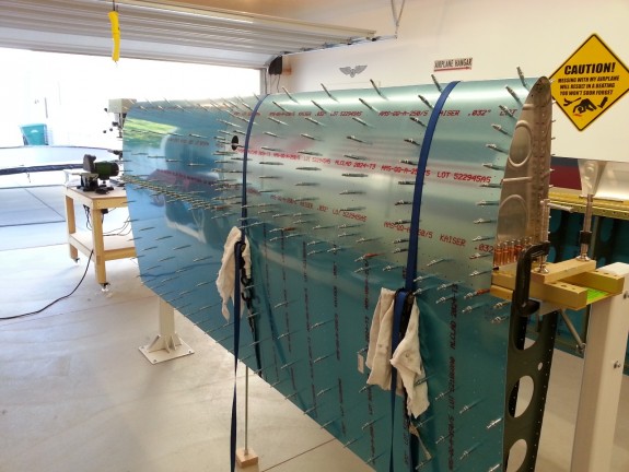
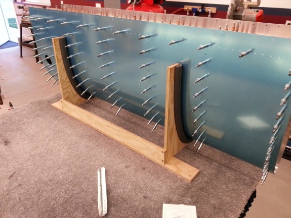
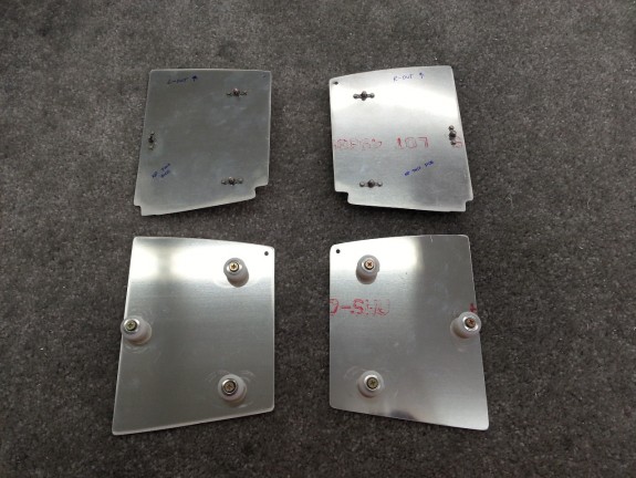
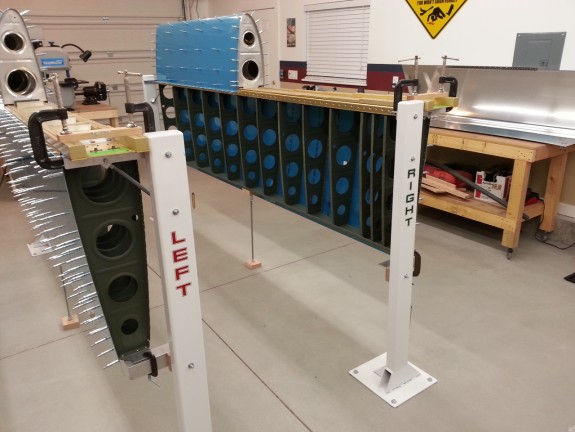
Originally when I thought out my wing stands, I thought that I would paint them red and green corresponding to the NAV lights on each, to differentiate between the 2 wings. Since my neighbor graciously painted them for free at his shop…I took what I got and was happy to do so.

So to get the same effect, I had my other neighbor with a vinyl cutter, make me some placards that could be used instead of paint.

Nerd question of the day…what is the font from? 🙂

Categories: Major Wing Sections

Inboard Rib Plumbing Penetrations Done

October 22nd, 2012 No comments

Inside the Inboard Tank Ribs

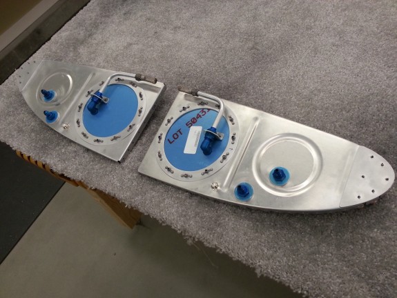
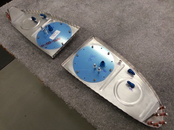
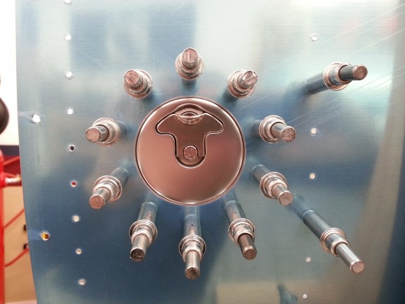
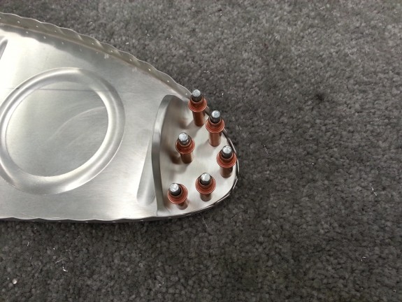
After giving some (OK, too much) thought to where I wanted to run the vapor return fitting, I finally settled on the upper part of the forward stamped stiffening ring. I opted for simplicity, so I also drilled a hole in each interior tank rib in the same location as the bulkhead fitting. This way the return fuel will dump into the most outboard tank bay and get cooled down by the rest of the fuel before being picked up again. Additionally, the return line will simply be a straight piece of tubing through the tank.

The holes were all 7/16ths for the vent and vapor return lines. The BNC hole for the capacitive senders are 3/8ths.

Outside the Inboard Tank Ribs

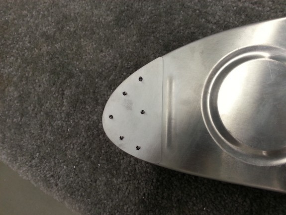
At this point I am ready to deburr all the rib holes, skin holes, dimple, scuff, and generally get ready to break out the sealant and get to final assembly of the tanks. Here you can see the penetrations from the exterior of the tank.

After getting this prep done, I cleaned up the shop and basically got things in order. It may be a couple of days until the next build session. Hopefully I will be done sealing tanks by Thanksgiving.

Categories: Tanks

Countersunk Cap Flanges, Plumbing Work

October 20th, 2012 No comments

Countersunk Cap Flanges

Spent yesterday at my Grandmothers funeral. She truly was a great lady in life. Family was still in town, but had not arrived at the house yet so I snuck out to the shop to see what could be done.

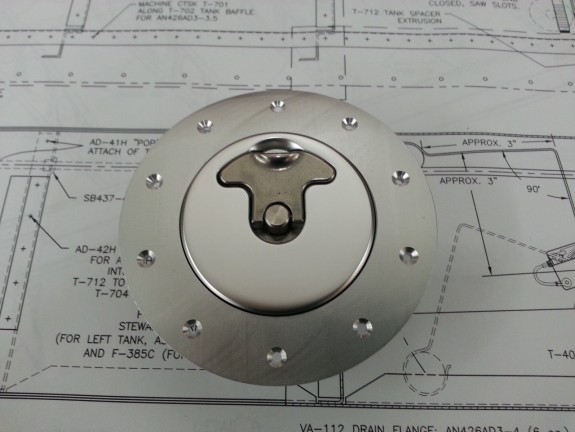
I was able to countersink the flanges of the fuel caps to accept the skin dimples. If you look at the full size photo (just click it) you can see the varying thickness of the flange that I mentioned in the last log entry. This was pretty painless. I love having a countersink cage for each size. I can set and forget for a certain setting. These are now ready for sealing and installation onto the tanks.

Drilled the Left Tanks Capacitive and Vent Penetrations

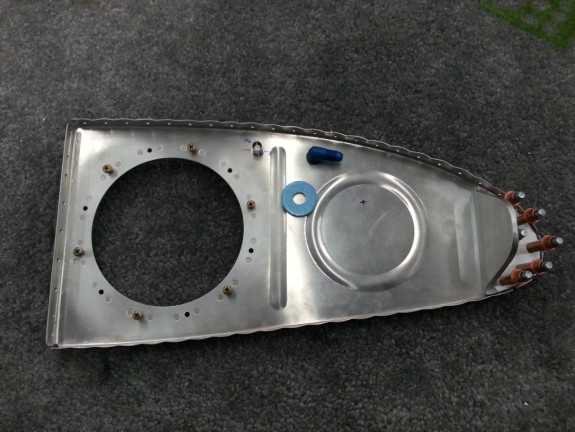
Next I was able to locate the vent and capacitive sender connection locations on the Left Tank. I still need to figure out where I want to put the vapor return line for the possible EFI setup. The washer you see in this picture is likely the location I will use. I also thought about putting it where the mark is on the rib inside the stiffening circle you see there. I do not know…but will decide in the next few days.

That was all that I had time for, so I closed up shop for the weekend.

Categories: Tanks

Drilled Fuel Caps

October 18th, 2012 No comments

Drilled the Fuel Cap Flanges

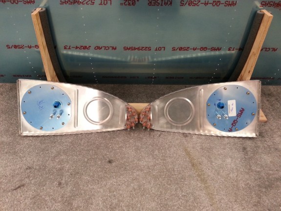
This week has been a little hectic as my Grandmother passed away last Friday. With all the ramping up to the funeral and family coming into town, time is short. I was able to get out to the shop and at least get the fuel cap flanges clamped into place and drilled. As you can see, I am using the “deluxe” locking caps. I have heard, and experienced, the stock caps. They are tough to open. These however are very nice and smooth in operation. I think they look nicer too.

The stock cap flanges are bent to match the curvature of the tank skin. These deluxe caps are machined to the curvature. The difference in the build is that you have to use all different length rivets on the deluxe where the same rivet length is used on the stock.

I centered the cap in the hole, clamped it in place and drilled each rivet hole. As I drilled one, I clecoed it, then went 180° and drilled that and clecoed. I followed a star pattern like you would when installing lug nuts on a wheel. Once complete, I checked the alignment again. Not that I could do anything about it, but for sanity sake. The look good to me. That was all I could get done for the day.

Categories: Tanks

More Tank Prep

October 17th, 2012 No comments

Prepped Capacitive Sender Plates

I set a goal tonight to get through a bunch of tasks and completed them all. First up was to get the capacitive sender plates prepped and ready. I started by laying out the positions of the plates on one set of ribs for one tank. Once match drilled, I then clecoed the corresponding rib from the other tank to the rib just drilled using the tooling holes. I then match drilled the ribs together. The accuracy of the parts to one another meant that my alignment should match the other rib just fine…and it did. I then modified the outboard plates to clear the stiffeners that are on the bottom of the tank. I did this all at once, filing both plates at the same time.

Next up was to countersink the plates for the platenuts. If I had really thought about it, I would have dimpled these and the platenuts rather than countersink. They really are too thin to effectively countersink. I was going to use “Oops Rivets” but that is a longer, boring story. Needless to say, dimple these, not countersink. I made it work however.

Once that was done, I cut the tubing that insulates the screw from the plates so as to not create an electrical path from the plate to the rib. I then deburred all the spacers as there was a lot of molding flash on them around the edges. I figured I would clean this off and eliminate possible contaminates to the fuel. I also cleaned out the inside of the spacer holes with a razor knife for the same reason.

I attached the platenuts and then proceeded to test fit the plates to the ribs.
Screw…is it or…

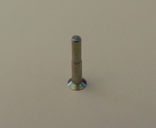
As I was grabbing screws blindly from the parts bin I put all the hardware in, I inserted one screw in the stack and tried to tighten it. I could not figure out why it was not threading. Everything was lined up just fine, but it simply spun. I decided to take a look at it and to my surprise, this screw did not have any threads. I chuckled a bit and then realized that I was now short the screw I needed to fit the plate on. Oh well, I will run to the FBO later tomorrow and likely have them comp me one to replace this one.
Fitted Pickups to Access Covers

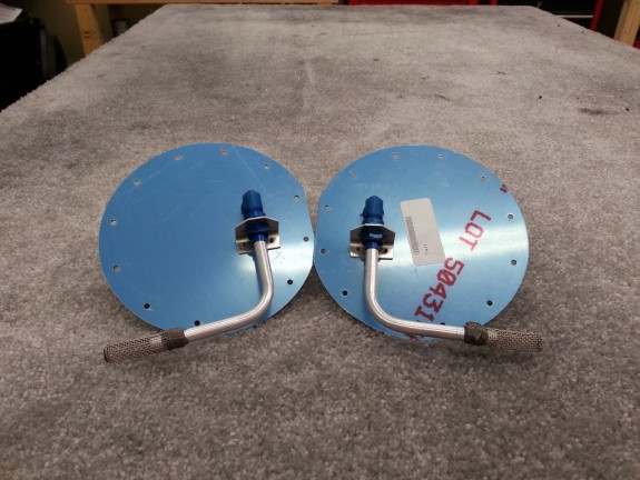
Once the capacitive plates were prepped, I test fit the pre-made fuel pickups to the now drilled blank plates. Everything looks like it should and the pickups appear to be in the right position relative to the tank for me to get the most fuel out of them. Granted, with a reserve, you should never have to worry about starving the engine…but it is good to know that you can get the maximum out of the tanks if needed. The pre-made pickups are nice and save a little time. I think worth the money and reduction of hassle.

Next up was to catch up on some other tasks I had neglected. I needed to cut out the stiffeners and match drill them on the left tank. I knocked these out pretty quick. I thought about calling it quits here, but was on a roll, so I kept going.
Drilled Sump Flanges to Skin

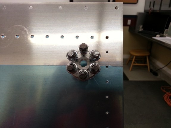
I centered the sump flanges on the skin by eye. I have seen some elaborate setups to do this task, but I guess I got lucky…mine look spot on. I did take some time to line up the flange as straight as I could, but in reality, if you are looking that close to my plane…you better be buying it. I knocked out both pretty quick and they are actually spot on.

I could have called it a night again, but instead, I decided to debur all the holes on the inside of both tank skins. By then, I was dead tired. So I finally called it a night…or at least early morning 🙂

Next up, I plan to finish prepping the inboard tank ribs with the capacitive BNC hole, vent fitting hole, and vapor return hole. I will also be drilling the fuel cap flanges to the skins. Then it will be time to debur, dimple, and scuff the parts. After that, time to start the dreaded sealing of the tanks. Yipeee! 🙁

 

Categories: Tanks

Started Right Tank Inboard Rib Modifcations

October 15th, 2012 No comments

Brackets and Access Covers Done

I was able to get the T-405-R fabricated, drilled, and match drilled to the right rib and T-410. I then cut the access hole with my fly-cutter and riveted on the platenuts and T-407 to the T-703-R. I also drilled the anti-rotation bracket holes and the holes for the fuel pickups. Not a lot of description, but basically a repeat of the last time I was in the shop.

At this point, it is time to fit the capacitive fuel level senders and the other fittings for the vents and fuel return lines for the fuel injection and these ribs will be prepped.

Categories: Tanks

Started Left Tank Inboard Rib Modifications

October 11th, 2012 No comments

Match Drilled the T-405-L to the Rib

With the T-405-L fabricated, it was time to drill it to the rib. I laid out the rivets as close to the drawing provided since there really is not a list of dimensions for each rivet anywhere, so it really is an “eyeball it” or best guess anyway. I simply worked it to insure good pitch and edge distance and drilled away. Once that was done, I inserted the bracket into the nose of the inboard rib of the left tank to prep it for match drilling to the rib.

Inside T-410-L Drilled to Rib

On the other side of the rib is the T-410 that also gets match drilled to the rib with the T-405. It creates a sandwich and also helps reinforce the nose of the rib. I also think it helps later in the sealing the nose of the rib with sealant by closing the gaps where all the tabs are. Here you can see the rivet holes drilled to the rib and the T-410-L.

Flywheel Cutting the Access Port Hole

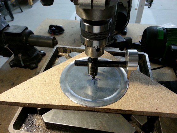
Once the nose was done, I moved on to cutting out the access port hole. It is a good size hole and I had to use my Fly Cutter. I have had this tool for some time [aka long before thinking about building a plane] since it works will to cut centering rings for large rockets. It was nice to have on hand to complete this task. It is actually a pretty quality tool. Some have used ones from Harbor Freight, that look as cheap as they are. Mine worked well. You can see here the center of the hole after I was able to finish the cut. Took longer to set up then it took to cut the hole in the rib.

T-407-L Riveted to T-703

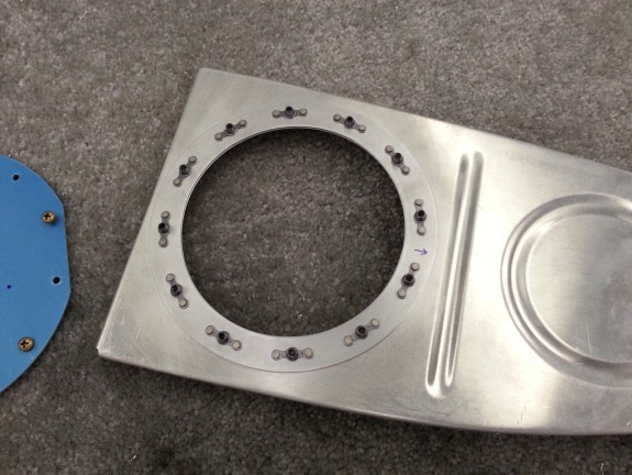
After deburring the new large hole in the rib, I located the position of the T-407-L reinforcement ring and match drilled it to the rib. This went pretty quick since I had deburred the T-407 some time earlier. I then countersunk the ring and dimpled the rib and used my pneumatic squeezer to attach the platenuts to the rib and ring. I really felt like I was moving along tonight.

Reinforcement Ring Installed with Platenuts

Here is the backside of the rib with the ring and platenuts. Looks pretty good to me. Since the plate is on the inside of the rib, there is no real need to seal it to the rib. Any leak path would simply return to the inside of the tank. The screws and rivets will be sealed by sealant when the access cover is attached.

Hard Parts Done

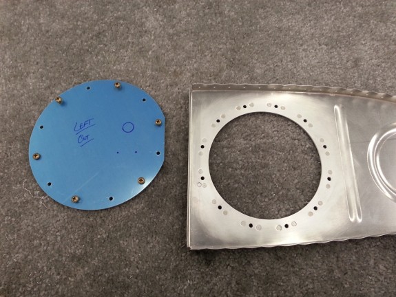
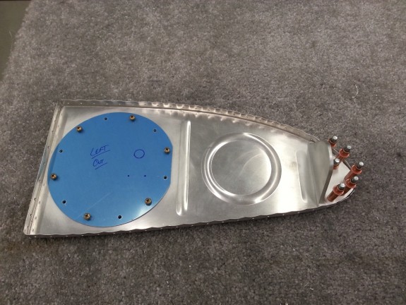
By the time the night was spent, I was able to slip the cover over the access hole and hand thread some screws to hold the cover in place. You can see here I have some markings on the cover. Since I am not using the float senders for fuel level, the stock covers can be tossed. However, the covers supplied with the capacitive senders are not pre-drilled for the fuel pickup. Some builders install flop tube pickups, so Van’s ships the covers blank. I simply used the stock cover and marked the location of the pickup tube and anti-rotation bracket holes for reference. I will eventually use the stock cover to match drill for the anti-rotation bracket. Then I will use a step drill to open the hole for the fuel pickup.

The time has arrived to decide if I intend to install a flop tube in one or both of my tanks. Short answer, I am not in either. I have read where they can stiffen up. I’d rather avoid maintenance issues inside my tanks. Additionally, in order to truly take full advantage of inverted fuel, you have to install fuel injection (which I am planning on) and an inverted oil system (which I do not intend to do) in order to enjoy sustained inverted flight. I just do not think that I will do any extended negative G maneuvers. Others report that they get 20+ seconds of good fuel flow without a flop. Again, do not think it will be something I want to add to my flying. So, I feel that I will get all the excitement out of my plane with standard fuel pickups and be just fine. I will still have good ability to do “gentlemen” aerobatics without the hassles of possible maintenance issues. That, and it conforms to the KISS [Keep It Simple Stupid] principles.

All in all, it was a great work session for an “after work” day in the shop. Next up is fabricating the T-405-R and repeating the above completed work on the right tank rib.

Categories: Tanks

T-405-L Fabrication Complete

October 10th, 2012 No comments

T-405-L Fabricated

Got a little shop time in and was able to get the T-405 for the left tank cut complete and deburred. It was kind of cool to take a raw angle and a drawing and make a part appear that looked like a real airplane part. Now the challenge is to mirror it for the right hand tank. It was late so I called it a night.

Categories: Tanks

Tank/Fuselage Attach Brackets Started

October 8th, 2012 No comments

Started Attach Brackets

Not a big progress night, but I started the brackets that support the tank at the inboard end tonight. I got this far and ran out of time. I will detail how I did them after they are done.

Categories: Tanks

Right Tank Drilling Done, Left Tank Started

October 6th, 2012 No comments

Right Tank Drilled and Sunk

I had a goal for the day. Get the drilling done on the right tank and get the Z brackets drilled on the left. I had match drilled the right tank skins and ribs earlier so all that remained was the rear baffle. I reamed all the holes in the skin to baffle and then set out to decide if I was going to countersink or dimple these. Vans tells you to countersink them to make installing the baffle easier when sealing the tank. I have read where others have successfully dimpled these, which is a stronger joint. I tossed the idea around and then decided to stick to the manual here. It does not seem right to countersink 0.032″ material, but it truly is the minimum you can. I tested a scrap piece with my countersink cage and once set, countersunk the holes. I had to remove the plastic to the point where my cage would sit flush to the skin.

Once done, I still was not liking the idea of the countersinks, but many a tank have been built this way and are flying fine. With these done, all that remained were the stiffeners to match drill.

Right Tank Stiffeners Drilled

I disassembled the tank and then clecoed on the stiffeners and match reamed them to the skin. Before removing them I marked their location so I could return them to the same place. With the stiffeners done, I then opened up the screw holes around the perimeter with a #19 bit. At this point the drilling is complete on the right tank [except for the fill cap and drain port]. I have a lot of prep to do for the capacitive senders and plumbing, but I will do those at the same time as the left tank parts.

Working on the Z Brackets on Left Tank

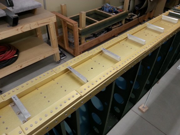
Now that I had all the clecos from the right tank, I assembled the left tank so I could drill the baffle Z brackets. Here you see the tank in place and strapped down. I had already drilled the inboard bracket and was about ready to remove the outboard leading edge to get to the inboard. I completed the outboard bracket and then took the skin and ribs off and drilled the rest of the brackets in short order.

Left Tank Brackets Drilled

With the brackets now drilled for both tanks, I will be able to get the tank prep done. The next time the brackets attach to the spars, it will be on a completed tank. Next up is match drilling the left tank, stiffeners, baffle, and then countersinking the skin to baffle holes. Then I will work on all the attachments to the tanks and start sealing away. I may have completed tanks by Christmas.

Categories: Tanks

Shop from Roof

October 6th, 2012 No comments

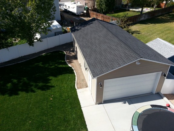
I had to get on the roof of the house to clear some objects the kids had tossed on it. While up there, I took an “aerial shot” of the factory. Enjoy!

Aerial View of Factory with New Yard

Categories: RV Factory/Shop

Right Tank Match Drilled, Stiffeners Deburred

October 3rd, 2012 No comments

Right Tank Match Drilled, Stiffeners Deburred

Short night, but I was able to get the stiffeners deburred and rounded and the right tank match drilled (reamed) except for the top and bottom skin to baffle holes. Not much done, but some.

Categories: Tanks