Archive

Archive for February, 2012

Elevator Final Push…Almost Done!

February 25th, 2012 No comments

The "J-Bolt" and Pipe Method

The time came to make the final push on the elevators. This meant rolling the leading edges. This step has been one that I have NOT looked forward to for some time. You can do really nice work the entire time, and one slip up here can ruin the whole assembly. I read many ways of doing this step. I also tried different ways when it came to rolling the rudder leading edge. The saving grace is that this step does not have to be “precise” as the leading edges are hidden inside the trailing edges of the mating parts. The one catch to this is that it should not rub the interior of the trailing edge of the mating parts through the full travel of the surface. That and you still want it to look “good.”

As I did with the Rudder, I took a tip from a builder over on VansAirforce.com where he used J-Bolts to hold a 3/4″ Electrical conduit to the table. This keeps the pipe close to the table and should make a nice radius. The other part of the setup is that you can drill the end of the pipe and insert a cross rod that can be used as a handle. Since you are not having to worry about holding the work to the table, you can use both hands on the handle. Supposedly you can also do all three sections of the roll at once.

So I taped the skin to the pipe using “Gorilla” brand duct tape. I think this is the same stuff the USAF calls “100mph tape” because it sticks great. I then anchored the pipe to the bench using the J-Bolts. Once I was committed, I threw my 3/8″ steel handle through the holes I drilled in the end of the conduit, and then twisted away. At first I thought…heck, this isn’t all that bad. The bends seemed to be a nice radius and all three sections rolled together nicely. This may look OK!

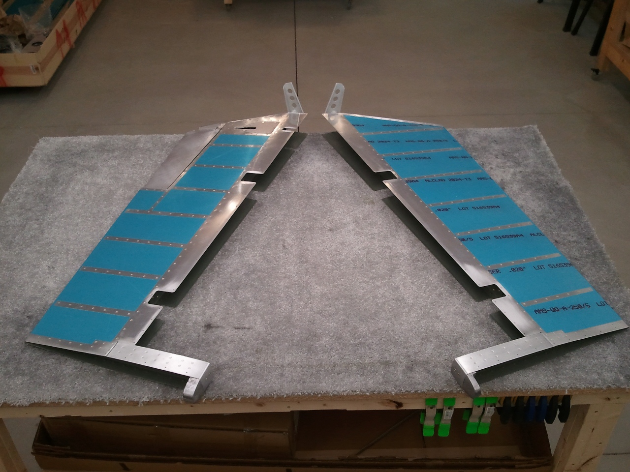
Left Elevator Leading Edge

Once I removed the tape and conduit, I took a long look at the bend. The one problem I see is that I think the J-Bolt setup makes the conduit TOO effective. The radius seemed almost too tight. I massaged it as much as I could, but I learned on the rudder that too much massaging can make the problem worse in a hurry. I was reluctant to massage more than I could have for fear this may occur on the elevators. Once the bend was done, I simply pulled the skin ends together and clecod the overlap. There was some squeezing by hand to close them, but not a ton. I then match drilled, deburred, and clecod them, and then pop riveted the leading edges together. The above was the result for the left elevator. I may be hard on myself, but I wished they would have been a little more smooth in the radius. I think this again had to do with the conduit being too effective with the J-Bolts. Most that are not using the J-Bolts simply roll the edge by hand while holding the assembly to the bench. The J-Bolt eliminates the need to hold it down while rolling. In the future, if I have to do it again, I may just use a bigger diameter pipe/stick.

Right Elevator Leading Edge

Here you can see the right elevator roll. Here you can see the tighter radius again. I tried to massage it a little more subtle, but I was still afraid of making a bigger mess than solving. As it stands, the joints at the overlap are nice and tight with no noticeable puckering. I am pretty sure they will function just fine.

End of Empennage MAJOR Construction

At the end of the build session, I walked out of the shop with two good looking elevators. This marks the end of the MAJOR portions of the Tail Kit. This is a big milestone. What’s left then?

  1. Mount Elevators to Horizontal Stabilizer and trim the lower flange of the HS-603PP to clear the elevator control horns for full down travel.
  2. Trim the HS-601PP skin to clear the counter balance arms.
  3. Drill the elevator control horns for the center pivot bearing and bolt.
  4. Fiberglass tips for the Horizontal Stabilizer, Vertical Stabilizer, Upper Rudder, Lower Rudder, and Elevators. (Will do these when the tail is mounted to the Fuselage.)

Once items 1-3 are done, I will store these parts away for safe storage and keeping and begin the WINGS! I will also call the empennage/tail complete!

Categories: Elevators

Trim Hinge Done…Again

February 24th, 2012 No comments

NO Edge Distance Issues Now

After waiting a few days for the replacement hinge to arrive, it was time to finish the elevator side of the hinge…again. This time, I left the hinge long and marked it with the skin on the inboard side…like the manual says to…DUH!

Since the new hinge came with a much longer than needed hinge pin, I bent it to the correct dimensions as well. I need to touch up the primer some, but eventually, this will all get painted with the base color when complete.

The trim tab moves silky smooth top to bottom and my worries about strength are no more.

Categories: Elevators

Elevators ALMOST Done

February 20th, 2012 No comments

Major Assembly of Elevators (and Empennage) Complete…ish 🙁

Another found and forgotten photo for the log. All done but the curling of the hinge line.

Categories: Elevators

Elevator Balance Mod

February 18th, 2012 No comments

Inboard Side of Balancing Modification

As I have read up on the balancing of the elevators, several good discussions have taken place on VansAirforce. One that I really liked was a suggestion from an RV-6 builder that simply enlarged a tooling hole in the forward section of the counter balance arm for a 1/4″ bolt. He then installed a nutplate to capture the threads. Once done, you can add a number of large AN washers to get the balance just right.

I thought this was a slick method. I did the same, just in case. It is much easier to do it now than later. So I enlarged the tooling holes, used some NAS1097 rivets and installed the nutplate for the bolt.

Outboard Side of Balancing Modification

Some have expressed some concern as the outboard side is covered by a fiberglass tip, so how do you get to the bolt? One suggestion was to make the tip removable by installing it with screws and nutplates. I do not intend on needing access to the outboard side after the tips are on. Another suggestion was to leave the bolt accessible on the inboard side. Then the concern was if the bolt worked its way out if it could jam the elevators.

I decided to install the nutplate on the outboard side and leave the access to the balancing bolt on the inboard side. I also bought drilled head bolts. This way I can install the balancing weights/washers and then safety wire the bolt head which solves the backing bolt head issue. As part of my preflight, I will simply check the safety wire as with all other safety wire on the surfaces.

Heck, if I am lucky, I won’t need it at all and it will balance just fine. Time will tell once it is painted.

Categories: Elevators

Left Elevator Riveted, Trim Tab Completed

February 18th, 2012 No comments

Ready for Final Riveting

Once the new trim spar arrived, I was able to finish the skin prep and prime both the skin and the new trim spar. Once the primer dried, I then clecod the elevator back together. Here you can see it is all ready to be finished riveted. I should be able to reach most, if not all, with my squeezer. I love that tool. It makes fast work of rivets.

Elevator Done, Trim Tab Hinge to Go!

Here is the elevator riveted together. I think it took me all of about 30 minutes to get this far. I also made the bends in the trim tab. I see now why people dread the left elevator. I had some real trouble keeping my bending blocks from slipping when trying to make the bends. Despite that fact, I think it turned out AOK. I scuffed up the skin in the process however. Since I am painting anyway, I figured I would simply scuff the whole tab now.

Once the tab was match drilled and dimpled, I primed the inside and the faying surfaces of the end tabs and set it aside to dry. I then went to work fabricating the hinge for the tab an the elevator. I was excited at the progress I was making and went to town.

I wanted to make sure that a complete barrel of the the elevator side would be located at the most inboard end. This also makes a complete barrel at the outboard end as well. I figured that this would limit any twisting forces that “could” occur, true or not. I marked the inboard edge of the trim tab side with the inboard edge of the trim tab. I did not however, do the same on the inboard side of the elevator half of the hinge. I simply cut it off flush with the last barrel and figured that would be good. I was wrong.

I positioned the trim tab to the elevator and clamped on the hinge and match drilled both halves to the respective parts. The trim tab half went just fine. I clecod it on and went on with the elevator half. After match drilling the hinge and removing it, I saw something that concerned me a little. The most inboard hole was busting the 2Xdia edge distance and really (and I mean really) close to being inside of the 1.5Xdia edge distance rule. I consulted a few smarter folks and they said I would likely be OK to rivet it on as is. So I did.

I finished the trim tab, inserted the hinge pin, stepped back and admired my nearly finished elevator. I typically do an after rivet smash inspection and looked again at the most inboard rivet on the elevator half. I just did not like it. It WAS too close to the edge. I also thought about where the most force would be transferred to the hinge. Since that is soooo close to where the trim servo actually applies the force to the trim tab, I bit the bullet and removed the elevator side hinge. I know, a whole row of rivets for one perceived mess up. I did not want the hinge to possibly tear out over time. After all, it is my plane and I needed it to be right, not close enough here.

I now needed to replace the hinge. I first called around to fellow builders and A&P’s to see if they had any AN257-2 hinge. Turns out, it is not common. Not to mention, after some looking, the only AN257-2 hinge on the plane is right here. Guess it was time to order one. I checked Vans’s and Aircraft Spruce. Turns out for the same money and probably the same shipping, I could get 3 feet of #2 hinge from Aircraft Spruce over 18″ from Van’s. Both would arrive the same day, so order was placed at Aircraft Spruce. You can always use extra at the same cost. All in all, it was a great build day and a good learning experience.


Categories: Elevators

New E-606PP Arrives

February 15th, 2012 No comments

No pictures tonight. The new E-606PP trim spar arrived and I ran it out to the shop. I slid it into position, matched drilled it, and countersunk the upper holes. This time I used the same matched drilled backer and the countersunk holes looked great. I then dimpled the spar, the skin and slid in the assembled skeleton previously done, and clecoed it all together for fun.

Hopefully this weekend I can prime the skin and spar and be able to get the elevator riveted together final. Then I can move on to the trim tab itself.

Categories: Elevators

Inspired by…

February 13th, 2012 No comments

Inspiration

Each year, my family attempts to give hand made gifts at Christmas to the siblings on a rotating schedule. We do not always succeed, but we try.

This last year my sister Amy had me on the rotation. Since she was aware that I had just built a shop to build a plane in, she commissioned a neighbor of mine that cuts vinyl to cut the motto of our Grandfather.

The idea was that I could put it somewhere on my shop walls for inspiration and encouragement.

I finally was able to get it stuck on the wall. It is now a central focus of the shop.

Thanks AMIS!


Categories: Hangar Chat

One Step Closer

February 11th, 2012 No comments

As far as the parts could go

Saturday came and it was a nice day to boot. I got some honey do’s done and then headed to the shop. Since prepping all the parts aside from the trim spar for primer, I knocked out spraying them. While the primer was drying, I took the time to remove the blue vinyl from the rivet lines on the skin, deburr it, and dimple all the holes except where the trim spar goes to be able to match drill it when it arrives.

I then scuffed the skin for primer but the temp fell to far to shoot it. So I looked at the assembly instructions for the skeleton and determined I could start riveting the parts together without causing any trouble to getting the new E-606PP spar taken care of.

The above shot is at the end of the building session. I was able to get the skeleton mostly complete. I love how it all lines up. You can also see my wire exit hole near the hole for the trim servo jack screw.

Everything went straight forward as it could have. I love having the right tools for the job. If you have not purchased a longeron yoke for your squeezer…do it now! As for now, I am as far as the parts can take me on the elevator.

Categories: Elevators

Left Elevator Work Resumes

February 9th, 2012 No comments

Dimpled and Scuffed, Ready for Primer

I decided now that I have heat, I needed to get back to work on the plane. It has been a few months and life has been busy. Since the last build session concluded with the match drilling being mostly complete, and I keep a good list of where I am in the manual, starting up again was a breeze. I got back to work prepping the rear trim spar (E-606PP) for the trim tab. I needed to disassemble the spar from the skin and countersink the upper holes where the hinge for the trim tab will go.

I set up my countersink cage with my piloted countersink to get these done. Here is where I made a small error. Since the spar is .032″ thick material, and the holes have to be a little deeper to accept the dimple of the skin, I forgot that it may open the hole a little more which will allow the pilot to no longer center and cause chattering. That is what happened on the first hole. Once the hole was opened up larger than the pilot, it made a real mess of the hole. The pilot was able to wander all over.

Some may say that the larger hole is a real problem. Traditionally yes it would if the spar being countersunk and the skin were the only parts being riveted together here. However, eventually the trim tab hinge will be added underneath, and this spar will be sandwiched between the hinge and the skin. There will be plenty of support for the shop head and the parts will lock together just fine.

So how do you keep the pilot from wandering? I grabbed a piece of scrap sheet stock and simply matched drilled it to the spar and clecoed it to the spar so that as I cut the material out of the spar hole, it still had a good hole for the pilot to continue to hold the cutter solid. This worked great for the rest of the holes that had to be countersunk.

Once the holes on the top were done, I dimpled the rest. As for the first chattered hole, I decided I would finish the rest of the hole prep and then decide what to do with this one. As I was dimpling the underside of the spar, I missed a hole with my dimple set in my pneumatic squeezer and punched a hole bigger. At this point, I decided it was time for a new rear spar.  As cheap as the parts are for the tail, it was an easy decision.

The rest of the night, I deburred, dimpled, and prepped the rest of the skeleton parts for primer. I did not dimple the skin tonight but will in the next build session.

I also added a 3/8″ hole in the E-702 spar just below the hole for the jack screw for the trim screw. I did not like the idea of the trim servo wire sharing the same hole with a piece of threaded rod. I centered the hole between the existing hole and the flange of the spar. It sits exactly centered with the existing hole as well. I think this will be a better way of routing the wire. I got the idea from another builder and have been told that no strength will be lost with a hole of this size here. Both holes will get snap bushings down the road.

It was now time to close up shop for the night and order the new trim spar.

Categories: Elevators

Fun with Blimps

February 8th, 2012 No comments

Glamor Shot

One of the things I love to do is give back to my community. If it can involve flying, all the better. While the particulars of the above are not public, the photo is. That is me sitting left seat as we were permitted to do a promo photo shoot for CAP. Needless to say, we are assisting the U.S. Army to help keep you safer at home. I love to fly and this is a neat project to be a part of.

Categories: Hangar Chat

Needed Upgrade Complete

February 7th, 2012 No comments

Heater Mounted to UniStrut

When I built the shop, I always intended to heat it some how. I insulated it really well, installed an insulated man and garage door, wired an outlet up in a corner, and wired a thermostat wire in the wall that went to the middle of the shop. I had a good idea of what type of heater I was eventually going to run and have been watching the local suppliers for good deals and something that would work. Since the shop was completed in April of 2011, there was no real pressing need to get a heater in at that point so I just put it on the back burner. 🙂

As winter began to approach this year, I began to think heavily about it again. When the temperature started dropping, so did my motivation to be in the shop working. As you can see, my build progress has been much slower since. The Holidays did not help either. I called a local RV’er that also does HVAC and we chatted about options, ideas, and costs. He gave me really good information, but shortly after, my money ran out as December 25th got closer.

As December 25th passed, we were blessed with some generous gifts from my parents and Grandmother. Combine that with a nice gal at Lowe’s giving me a good one time discount, I was able to get a 45000 BTU shop heater for a really decent deal. I also got the conversion kit to make it run on Propane for REALLY cheap as they were closing the kit out. I also bought the flue kit made by the manufacturer. All in all, I was out the door for no more than $400.00.

The 45000 BTU is rated to heat a 700 sq/ft garage. My shop is 720 sq/ft but really well insulated. I figured, it would be great fit as most garages are not insulated that well.

The heater is set up with mounting brackets that will natively mount to a 24″ on center truss situation. Here was challenge #1. I wanted the heat to be blown into the major area of the shop, not against a wall 16 feet away. I was sitting in my desk at work, contemplating how I could rotate the heater 90 degrees and still make it look good. Above me are cable racks suspended from threaded rods that hold pieces of UniStrut which the cable trays set on top. Solution found. I will get some UniStrut and mount it across the shop trusses and then hang the heater from them. Worked great. I painted the UniStrut so it would look good against the ceiling.

Double Wall Vent Done

I ran the wiring and installed a switch. Probably not required, but not a big deal in case it needs to be worked on. I can also just unplug it from the wall.

Next up was the vent flue. You can vent these in 2 ways. On is a traditional vertical flue and the other is a horizontal. I thought long and hard about both. I have a low pitch roof (4/12) and I filled the attic with R60 worth of insulation. It would have made a real mess and some real work to get to the spot where this vent would penetrate the ceiling and the roof. The horizontal required at 7″ hole to be cut in my fairly new wall and exterior. As you can see I chose to do the horizontal.

I began to use the flue kit that the manufacture designed for the heater and quickly realized I paid too much for too many parts for a simple run through the wall. So I boxed it up and returned it. I then ran to a local HVAC parts supplier and bought only what I needed. Saved nearly half over the manufacturer kit and got only what I needed. If you are going through the roof, the kit is nice and you will use most of the parts, but horizontally, it is not worth it.

The Exterior of the Vent Flue

Here is the view from the outside of the shop. The vent is required to be at least 12″ beyond the exterior. This is 12.25″ and looks just fine. It must also be 4 feet from any vented soffit. Since my eve is not vented here, not an issue. This is on the back of the shop…so I will never see it. My Dad suggested I put a smiley face on the cap for my neighbors to dress it up. 🙂 Nah.

Gas Line Anchored to Shop Wall

Next up was installing the hard line from near the foundation, through the wall, and to the heater. I simply used more of the same UniStrut I hung the heater from inside. Since my exterior is vinyl siding, and lagging the UniStrut right to the wall would squish it, I had my machinist friend make me some 1″ dia 5/8″ thick standoffs. This way the siding still floats around the standoffs, but the UniStrut is SOLID to the wall. I then drilled a 7/8″ hole in the wall for the 1/2″ black pipe to penetrate through. I then used the standard clips to hold the pipe to the UniStrut. Needless to say, you can hang off this pipe. I also found an off the shelf can of paint that matched the color of the siding and painted all the exterior parts for both corrosion resistance and so it would blend in to the building better. I think it looks great. Again, all this is on the back of the shop. Out of site out of mind.

At this point I can either run a Natural Gas line to this drop or I can drop a large Propane tank. This pipe will work for either and meets code.

Gas Line Plumbed

Next was the interior hookup. I asked about a dirt leg in the line and was told that they are not required here. This was especially true given the rise in the line to the heater. I can always add one later, but none of the appliances in my house have them and they have been good for many years. I painted the interior portion of the pipe white to blend in. I also put a cheap trim ring near the wall. Overkill to some, but a cheap way to dress it up a bit.

Now was the time to decide which gas. To get Natural gas to the shop is a BIG deal (and would have during original construction as well). I have to trench 18″ deep about 100 feet from the other side of the house without chopping through my sprinkler, telephone lines, pay to have the line installed/inspected, all while the ground is frozen solid. Not sounding like a fun winter prospect. I did buy the Propane conversion kit. I can have a local LP company lease me a 125 gallon tank for $48.00 a year and then I pay for the fuel at a reduced bulk price and no delivery fee on a schedule. The local HVAC/RV’r did a cost compare and that did not help me decide one way or another as some have convenience over $$ perks that come out nearly at a wash.

I have decided in the short term to convert the heater to LP and get the tank. As the winter thaws, I may then decide on the NG line and work and then convert it back to NG. If the consumption of the LP is low enough, I may simply keep the big tank and then have a backup in the event of a NG shortage. 😉

Heat, Glorious Heat!

I converted the control valve to LP. Changed the pressure spring and the burner orifices, and then hooked up a standard 20 lb Propane cylinder to test it and set the proper manifold pressure. With a flip of a switch on the thermostat, I had glorious blue flames. Within 10 minutes of running it, I had increased the shop 10 degrees! This thing is surprisingly quiet. I had to turn it off after a bit because I was tempted to run the whole cylinder. I think this will be a VERY nice addition to the shop. The bonus is that I can run only the fan in the summer and it will circulate the air and help with cooling.

Heater Ready to Run

So here it is all buttoned up. I still need to schedule with the LP company and get the tank dropped and filled. I adapted the exterior pipe to run off a smaller cylinder until then. It looks a little silly to have a small tank attached to the shop…but, it will do in a pinch until the big tank arrives.

Again, as it warms up, I can always trench, get a NG line installed, and convert it back to NG. But for now…I am loving this little heater. Now, it is time to get back to building the plane.

Categories: RV Factory/Shop