Archive

Archive for the ‘Empennage’ Category

NAS1097 or not to NAS1097…There is no Question

October 15th, 2011 No comments

Already Came in Handy

For some time, I knew the time was coming that I would need to install some nut plates to hold some screws that hold down things like access plates, fairings, etc. One of these places appears on the elevators. There is a doubler on the left elevator that allows for access to the trim actuator, be it electric (what I am doing), or manual. Basically, the doubler creates a flange inside the elevator skin that an access plate then screws into closing up the hole flush with the elevator skin. You find these access holes all over planes so you can service the aircraft in the long term. The trick is, that on a plane where flush rivets are used, you want your access plates to also use flush type fasteners. This requires dimpling the access cover and using flat head screws. Nut plates can be used with either as they are designed with a recess to allow for a dimpled doubler or can simply be attached to a flat skin to provide a nut on the backside. In all cases however, the fasteners that attach the nut plate to the airframe must be flush so that the access panel can lay flat against the doubler.

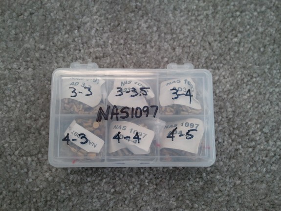
One of the things that I read up on was how people install their nut plates. There are two methods that work. One is to dimple the skin and the nut plate to accept a standard AN426 rivet. The risk here is that you can really mangle the ear of the nut plate as there really is not much material on them to dimple. The other is using NAS1097 rivets. These have the same shank size as their standard AN426 counterparts, but they have a shallower head. Since my local supplier required a 1/4 lb minimum purchase of each size at nearly $90.00, I found a kit by Avery Tools that met my needs. It has 2 different diameters with 3 lengths at 3/4 oz of each. You can buy many of these kits for the $90.00 required for one size. I think it will hold me over for many a nut plate.

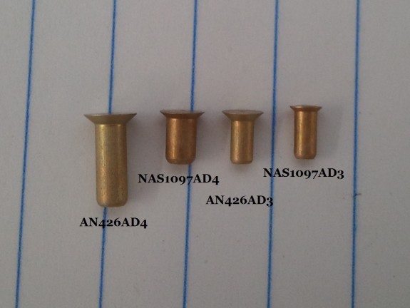
Side by Side of Shanks

What is the advantage then? Well, instead of having to dimple the skin and the nut plate, you simply can countersink the skin very lightly and then insert the rivet in the hole and nut plate ear, and smash away. Since the rivets on the ears are simply keeping the nut plate attached to the assembly and keeping the plate from turning when a screw is inserted, the fastener is really only working in shear, not tension. As you can see from the picture above, the shanks of the rivets are the same across the diameters. You can also see that the shoulder of the rivet head is much more shallow. Where countersinking may cause a knife edge with a standard rivet (countersink goes to the backside of the sheet), you can countersink thinner material and still get a flush head. Again, the force is in shear when you are screwing in a fastener to the nut plate, so the shank is the more critical portion of the rivet.

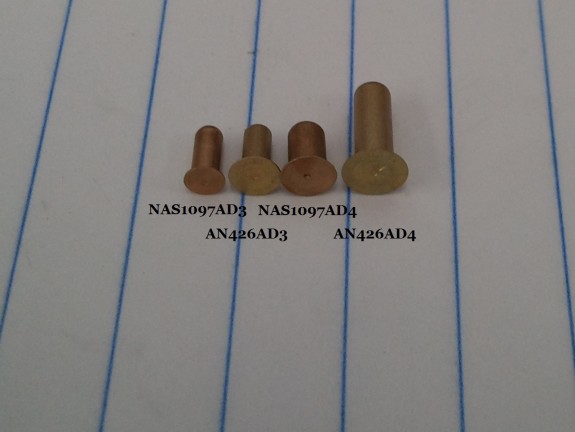
Side by Side of Heads

But wait…there is more to these. Say you are doing an assembly that requires 3/32″ (AD3) rivets and you bugger up the hole they go in really bad? In that case, you still have some saving grace. Notice in the above picture, that the head of the NAS1097AD4 is the same diameter as the AN426AD3! You can replace the AD3 rivet that is now undersized with NAS1097AD4 and from the top, you would never know it was different. Now…you cannot do this to all of them in a row mind you…but 1 in 10, you will be OK. That is why these rivets are referred to as “Oops” or “Fixit” rivets. As it turns out, I had exactly that happen to me as I was back riveting one of the elevator stiffeners. The AD3 did not set very well and when I drilled out the rivet to replace it, I noticed that the hole was now too large for a new AD3 but I had good edge distance, so I opened it up to a #30 and slipped in a NAS1097AD4. I am not telling where and you will never know once the elevator is closed up!

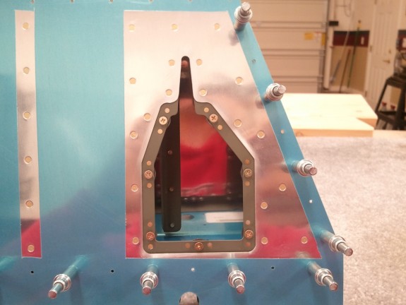
NAS1097's at Work

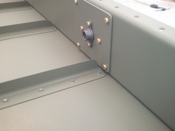
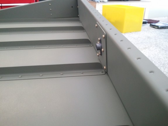
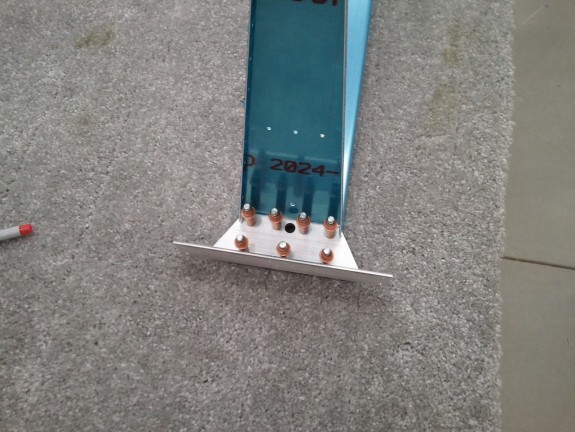
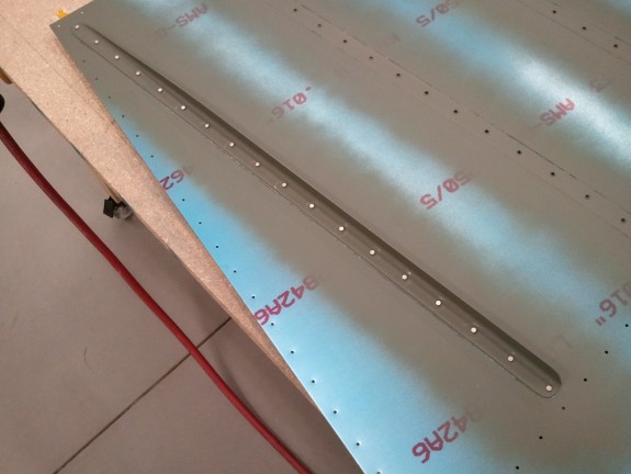
Here is the trim access hole with the doubler in place. You can see I have inserted the screws into the nut plates center. The NAS1097AD3’s are on either side of the screws. You can also see the difference in head diameter with the standard AN426 rivets that hold the doubler to the skin. They have the exact same size shank. A simple turn of the debur tool can produce a decent countersink, but I chose to use another little jewel I picked up with the rivet kit.

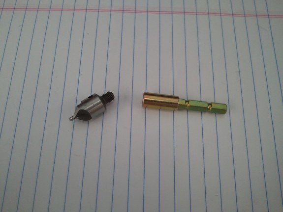
Could Prove Dangerous!

Basically, it is a chucking adapter with a threaded female side so I can thread in my countersink/debur bit into it and chuck it in a drill. This allowed me to more accurately and lightly countersink the doubler for the smaller head. Once all the countersinks were done, I hit the doubler with a shot of primer and let it dry. Once dry, I back riveted the doubler to the skin and then went back to prepping the stiffeners and skins for primer and back riveting.

 

Categories: Elevators

Elevator Skins/Stiffeners Primed

October 14th, 2011 No comments

One Half Now Primed

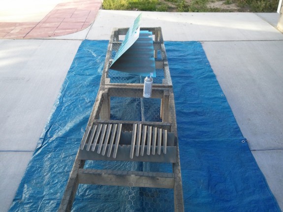
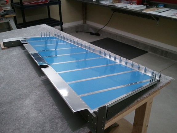
The weather in Utah is changing fast. This could be the last week of really nice temperatures outside. So when I got home from work, it was straight out to the shop to get the skins and stiffeners ready for primer. After all, I needed parts ready for a build session on Saturday. So I spent the remaining 70 degree daylight hours shooting primer. Here are the right elevator parts drying. I repeated the same for the left. Armed and ready for the weekend. πŸ™‚

Categories: Elevators

Skins and Stiffeners Ready for Primer…Almost

October 13th, 2011 No comments

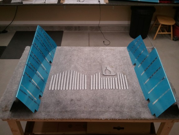
Ready to Prime

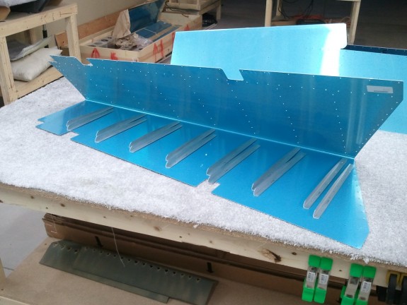
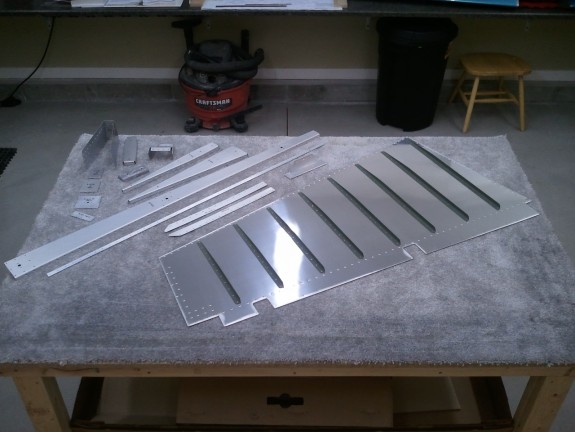
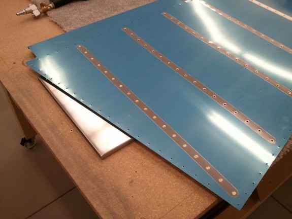
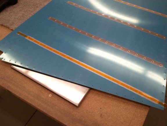
After work, I had some free time, so off to the shop. The first thing I tackled was dimpling the trim servo doubler (E-615PP) screw locations with my #6 dimple dies in the DRDT-2. These holes are REALLY close to the edge of the part, but they came out nice and crisp. I then swapped the dies for my 3/32″ and then dimpled all the rivet holes except the rivet locations for the nutplates that will be attached to the doubler that hold the screws for the access cover to the trim servo. I have decided to use NAS1097’s here instead of trying to dimple the doubler and the nutplates. These are commonly referred to as “oops” rivets. Why you ask? I will post more about them later when they arrive.

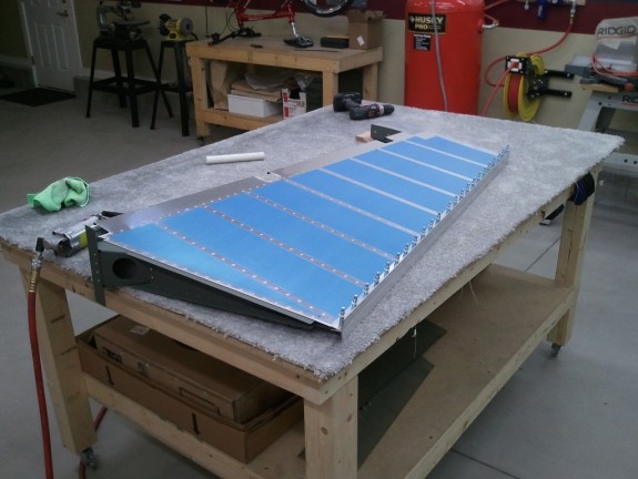
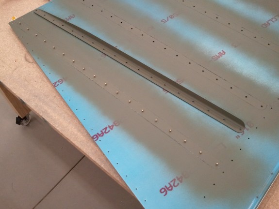
The next item to hit was removing the vinyl off the outside and inside of the skins at the stiffener locations. I have decided to do what I did on the inside of the rudder with the inside of the elevators. I removed the blue vinyl where the stiffeners go, and then I will scuff those locations and prime. Then when I am ready to close up the skins I will peel the rest of the vinyl off and lightly coat the rest of the interior of skin with some primer without scuffing. This appeared to work well on the rudder skins, and gave it a hair more corrosion resistance.

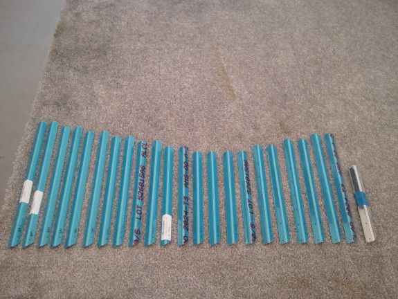
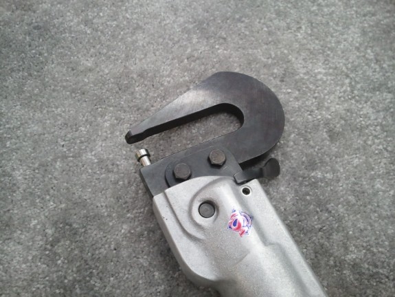
Once all the vinyl was removed, I dimpled the skins in the DRDT-2 and the stiffeners with my pneumatic squeezer. I then cleaned up and re-labeled all the stiffeners. All that is left is scuffing the inside areas of the skins and to prime them and the stiffeners. Then I will be ready to back rivet these little buggers on. With the weather warming up for a few days, I just might get it done this weekend.

Categories: Elevators

Elevators now in Process

October 10th, 2011 No comments

Stiffeners Trimmed to Length

One of the reasons I love working for a bank is the extra week of days off. Columbus Day is just one of those occasions. I am starting to get a real collection of air plane assemblies and need to find a way to get them up and out of the way. I have some ideas, but rather than tackle that right now, I decided to get started on the Elevators with my free time.

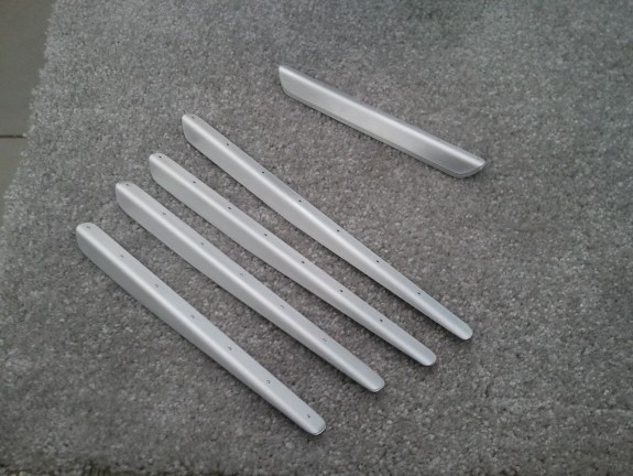
The first thing to knock out is getting the stiffeners cut to length and then trimming to specs. Here is where having the right tools makes quick work of a tedious task. I simply took my snips and trimmed to nearly the rough shape. Then I hit each with my 12″ disk sander to finish up the ends. As for the tapers to fit in the trailing edge, I took my band saw with a new blade and trimmed them to close to the cut line. The new blade went through these like a hot knife through butter. Once close, I went back to the sander and cleaned them up to the trim line.

Stiffeners Tapered and Scuffed

All that is left is to then hit the edges and round the corners to final shape and deburr. My scotchbrite wheel made quick work of this task. After they were to final shape, I simply scuffed them in prep for primer now. I like to get the not so pleasant tasks all out of the way at once. At this point, they are now ready to match drill to the skins.

Ready to Match Drill to Skins

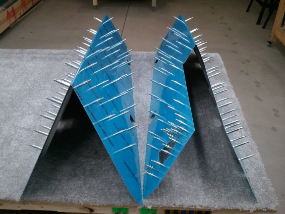
Here they are getting ready to be clecoed to the skins. There is one for the top and bottom of each skin. I took some time to label each before drilling so I could relocate them to the same spots once the drilling was complete.

Time to Match Drill

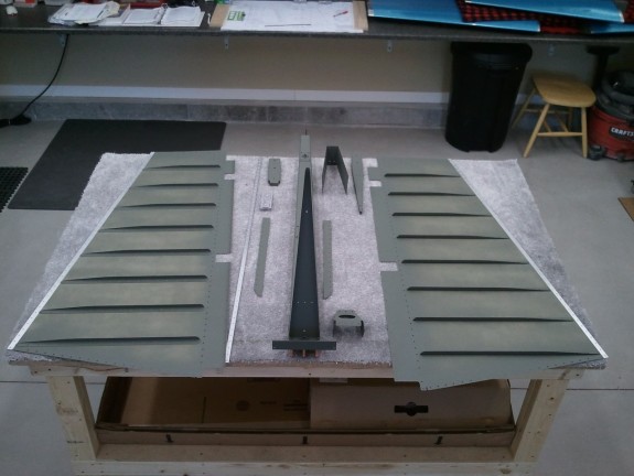
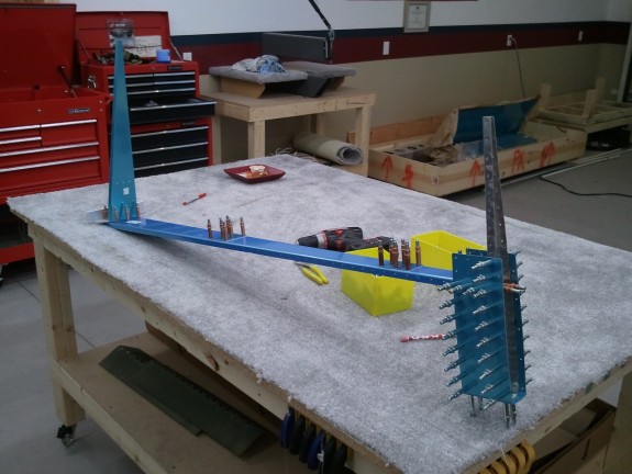
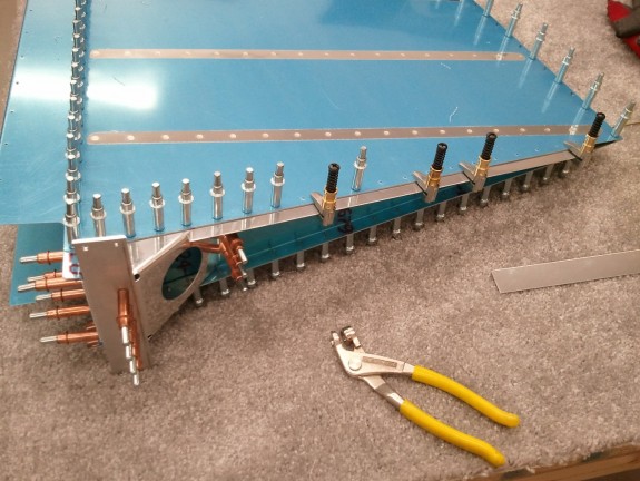
So here are the two skins ready to get at the match drilling. The skin shown on the right is s a little different. It will contain the electric trim servo and trim tab. It has a doubler/reinforcement that is match drilled at this point as well. So I went to using a #40 chucking reamer and matched all the holes….except…the last holes in the trailing edges that were not pre-punched in the stiffeners. I am not real sure why these are not pre done other than perhaps in providing the stock to make the stiffeners, it is easier not to since there is a slight difference in the length of some of them between the right and left halves of the elevators. That, or builders could confuse them when building and ruin them. Either way, there are 3 holes in the skin on each side of the skin that need to be used as a template to drill the final holes in the stiffeners. So I chucked up my #40 bit and got to it.

Joined the "Club" Bottom Side

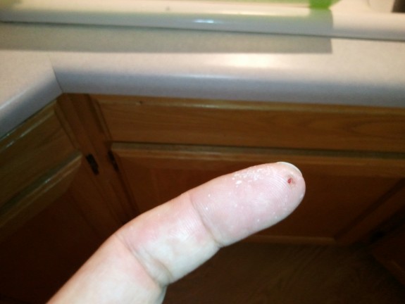
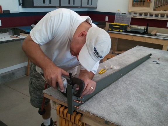
Then I found out the reason these are not pre-punched. Apparently there is a list of “clubs” or initiation rights an airplane builder has to join/pass to be full fledged. One of those is to drill your finger at some point. In Van’s great wisdom, they created a perfect storm to help you accomplish one of these rights. I was reaching in to hold the stiffener to the skin from the backside and drilling from the other side. This means you are essentially drilling blind to the backside. I thought I had gauged my distance from the hole further on down the stiffener well enough. At his point I had made it through 9 of the 12 holes that had to be done this way. On hole 10…something felt very different as I broke through. It then dawned on me…that is my finger!!!

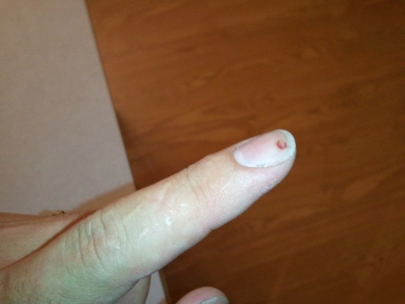
Joined the "Club" Top Side

Now that I realized that my #40 bit was now in my finger, I backed the drill out and extracted my hand from behind the skin. Yup…there it was…my entry into the “club.” I went though most of the meat of the end of my left index. I stopped just short of making a hole in the nail. As you can see…that is all the way through. I actually did create a hole in the nail but it did not break away. Fortunately my bit is very sharp. I stopped just in time to keep it from tearing out any meat so in reality, I simply created a deep spiral cut that when the bit was backed out, it closed up and stopped bleeding pretty quick. I irrigated it really well, threw a bandage on it and went back to the last 2 holes.

Once the match drilling was complete, I removed all the stiffeners, deburred all the holes in them (not the skins yet) and cleaned up the trim servo plate. They are all ready for dimpling and priming now. I will then need to deburr the skins and dimple them and then prime the inside. We’ll see if this hole in my finger slows any of that down.

Categories: Elevators

Rudder Complete…for Now

October 1st, 2011 No comments

Turned out Nice

Once the trailing edge was dry from the tank sealant applied Thursday, it was time to close it up. I was still a little nervous about the double flush riveting that had to be done. The manual does a good job describing the procedure, but it is still somewhat daunting. I decided early on that I wanted to alternate the manufactured and shop heads side to side for balance. May seem trivial, but I wanted a more symmetric appearance from side to side.
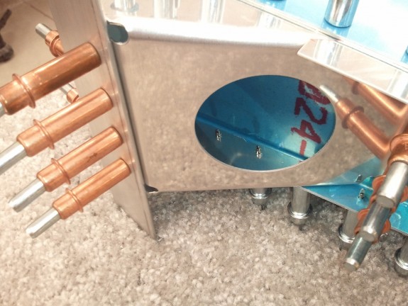
I pulled off the two angles and clecos and was pleased to see a straight trailing edge all glued up. I had a bit of cleanup to do with MEK to get the oozed sealant off the skins. There was a bit in each hole as well. I simply ran a #40 bit by hand through the holes to get the sealant to break at the edges of the holes and pulled out the little ball. Some of the dimples were filled so I lightly ran a countersink bit in them and it cleared it right out.

Now that it was all cleaned out/off, I set a rivet in every other hole and taped them in. I then flipped the rudder over and made my first mistake. I put my mushroom set in the gun and started to “half set” the tails starting from the middle of the rudder and working my way out alternating the sides from center. The mistake was using the mushroom set. It is simply the wrong set to use at this point. About halfway through setting these, the set slipped and I dented the skin near the spot where the skin and the AEX wedge meet underneath with the heal of the mushroom set. At this point I should have realized I was not using the right set. I did it once more and then figured out what was wrong. Filler at paint will hide the dents just fine but it was still aggravating.
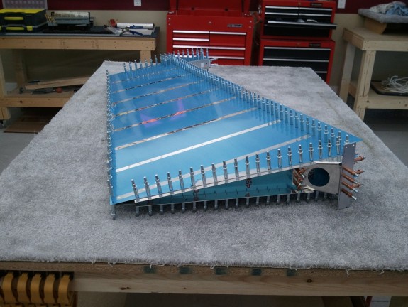
Once I realized I should have been using my back rivet set to “half set” the tails, all started to flow. I simply angled the set enough to push the tail into the center of the dimples and then rotated the set to be parallel to the skin. The head of the set never came close to the skin…duh! I got all the shop heads set, and then flipped the rudder over. NOW you put the mushroom set in and smack the manufactured heads over the back rivet plate. After a few…I realized I was getting it…too bad it took some dents to get there.

Once all the rivets were smashed into the dimples completely, I repeated the process with the remaining holes with the manufactured heads on the same side of the “acorns in the dimples” now complete. You can see the result above. They look great and the trailing edge came out straight and within tolerance per the manual.

Looks Done to Me

Here is an overview shot of the rudder trailing edge complete. Nice and sharp and pretty straight. The next step was to then roll the leading edges to complete the assembly.

Leading Edge Rolled OK

I wanted to get a nice clean joint along the leading edge. Prior to rolling them, I decided to use a nifty tool I got from Cleaveland Tool that forms the edge of material that will be lapped over another sheet. Basically, it bends a very gentle lip on the edge of the sheet so that when the two sheets are overlapped and then riveted, it makes a nice tight joint. I learned another valuable lesson here. NEVER try a tool for the first time on an assembly. Either mine is defective, or I do not know how to use it…but I mangled up one of the tabs on the top overlapping skin of the leading edge portion. Basically, the roller of the tool with the lip on it did not ride the edge as it is designed, but it rolled past the edge of the tab and made a mess of that edge. I was simply deflated. NEVER EVER use a tool on a part until you have mastered its use. I was able to get most of the mess out by using a wooden block with a slot cut in it about 1/4″ deep to straighten out the mess the tool made and then hand bend a flange in the tab…but the Cleaveland tool had stretched the metal in some places that was simply not going to be 100%. Aggravating to say the least. I will be practicing a TON more on scrap with this tool before it ever touches my plane again. The video below makes it look easy…mine did not work out so well.

I did not take too many pictures of the rolling procedure. Basically, I took a method I saw on Vansairforce.net which used some “J-Bolts” and a pipe. Instead of using the “J-Bolts” I used “U-Bolts” that could be locally sourced. First, you duct tape the skin edge to a section of 3/4″ metal electrical conduit. I used gorilla tape. That stuff beats duct tape hands down. Then once the pipe is taped to the edge, you “U-Bolt” the pipe, with the skin you are rolling face down, to the bench leaving enough slack in the bolt tightness so the pipe can be rotated. The “U-Bolts” hold the pipe to the bench at the hinge locations allowing you to twist the pipe and roll the skin all at once. As you twist the pipe, the control surface will slide along the bench as the skin is rolled. It worked great. I was left with a decent radius on both skins.

After the skins were rolled, I simply clecoed them together and worked the radius a little more by hand. Then I match drilled and deburred the holes to a #30. Here is where the mangled tab edge created earlier showed its problems. Many builders report little puckers between the rivets when the finish this part. Mine did the same on the center tabs. If I had not had issues with the edge forming tool, I think I could have had a really nice overlap on the center section. Needless to say, where the metal was stretched by the tool, my puckers are not pretty. The upper and lower overlaps look pretty good. Either way, this particular area will NEVER be seen unless the rudder is removed from the plane. Even at full deflection, you cannot see it, so…I am calling it good enough for now. At 200 mph and FL20, it will not make a difference in flight. If it REALLY bothers me when the plane is ready for paint, I may build another rudder. Unlikely as this one looks good otherwise and is very structurally sound.

Rudder Complete

We end the day with a glory shot. I had a conference meeting to attend after the build session and my lovely photographer was busy all day. So I convinced her to take a picture of the finished rudder right before I left. I think I may have the record for the most cleaned up glamor/status shot out there. All in all a good day. The fiberglass tips are all that remain. Time to get started on the elevators now.

Categories: Rudder

Trailing Edge Glue Up and Set

September 29th, 2011 No comments

I think that is straight enough.

After a record breaking weekend of flying the “Spam Can” Sundowner for my Birthday, the family needed to recover. I was not looking forward to gluing the trailing edge together using the Flamemaster sealant I was able to procure locally. I have heard it is nasty stuff and hard to work with. The time came however and the night’s schedule was open so I figured, what the heck…time to get it over with.

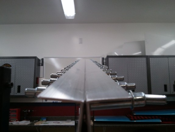
I had already taken the time earlier to make up two pieces of aluminum angle to support the trailing edge during glue up and cure. The plans call for only one, but I chose to double up so that I could cleco from both sides of the rudder and have something to grab into. Additionally, the two stiffeners insure that the clamping force is evenly distributed to both sides and both skins.


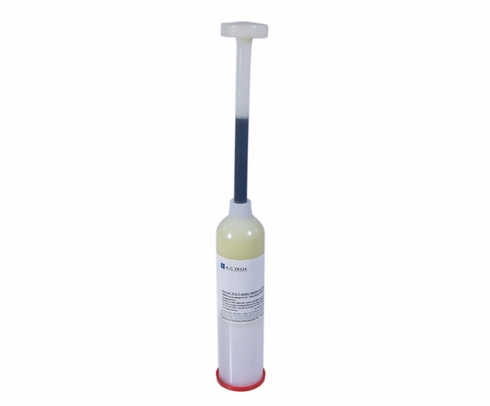
Fancy Tank Sealant Cartrige

So now the moment arrived to get the sealant mixed and applied. I followed the instructions per the package and turned the white tube black. I do not have a dispensing gun yet so I simply took a piece of 1/2″ PVC pipe to push the plunger from the back and squeezed out enough on a paper plate. I then used a Popsicle stick to spread a thin even coat on both sides of the trailing edge AEX wedge. Be sure to wear some form of disposable glove when working with this stuff…it is sticky and very messy. Also make sure to remember which way the AEX belongs in between the skins. You do not want to have to take the AEX out and flip it after this stuff is on it.

Once the AEX was smothered and back in between the skins, it is time to take some MEK and wipe down the globs that may have squeezed out from the rivet holes and the trailing edge of the skins. I additionally took the tail of a #40 bit and pushed it through each hole so I could wipe it from the other side and free up the hole for clecos and eventually rivets with little mess.

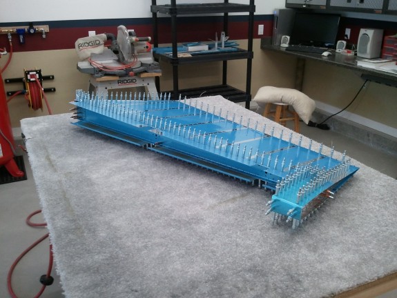
I then reinstalled the aluminum angle on both sides of the trailing edge and clecod every other hole starting from the middle and worked ever other side of the middle out. I figured this would line everything up and keep it straight as it was squeezing the goo out. I then flipped the rudder over and clecod the other side the same way. I felt that this was a good way of truly getting the same clamping force on both sides. It appears to work fine. I then hit the trailing edge with a MEK soaked rag to clean up the little that was collecting between my two aluminum angles. As the picture above shows…it is pretty darn straight. Excellent!

Curing the Sealant

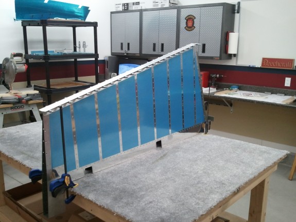
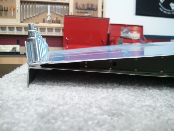
Once the assembly was wiped and clecod, I needed to set it aside so that it could cure. I noticed when assembling the rudder for riveting, that once the counter balance was installed, the rudder would get a slight twist in it sitting on the bench. I shimmed the counter balance when doing the perimeter to minimize the twist and it seemed to work. I also saw the slight twist when I slid the gooped up AEX. To eliminate the twist all together while the rudder was curing, I decided to mount the rudder vertically on the bench. so that the counter balance was pointed down and thus removing the problem. Here you can see the setup. I simply put clamps on either side in case it decided it wanted to fall. The carpet did great at allowing the non bent leading edge of the skins to sink into the carpet while the bent edge stayed afloat on the surface. They sat pretty level and allowed the rudder to sit vertical on the bench at rest. Here the rudder will sit for a couple of days curing. Once cured, I will then set the “acorns in the dimples.”
Categories: Rudder

Pop and Build On!

September 19th, 2011 No comments

Pop and Go!

I have spent a good amount of time trying to figure out just how builders are getting the last 2 rivets in the upper rib of the Rudder set. I just do not see how it can be done. Sure there are techniques, but I have tried a few with little success. These little buggers are simply too tight to get at. I was pleased I was able to get to most with a squeezer and bucking bar…but it was time to admit defeat and take the safer and just as adequate route. Above you can see my work for the day.

I simply took a 7/16ths bit and opened up the holes in the last two dimples of the upper rib. The MK-319-BS blind rivets that Van’s state can be used here went in with no issues and look OK from the outside. A little filler at paint or even a small amount of JB Weld in the mandrel hole and shaved off and you would never know the difference. The biggest plus is that it is simply done and I did not risk mangling up the rudder trying to buck rivet solids in. At 200 mph and 15000 MSL…you’ll never know I cheated! πŸ™‚

Now all that is remaining is the leading and trailing edges. Hope to get them done in the next week.

Categories: Rudder

Riveting as the Space Gets Sparse

September 15th, 2011 No comments

Almost Ready to Tackle the Trailing Edge

Today at work, the USPS Santa delivered a couple of new tools. I have been meaning to buy a no hole yoke for my squeezer and since the last rivets on the top and bottom ribs are really hard to get to the shop head…it was time to take the plunge. So I hurried home, took care of some “honey-do” items and then set up the new yoke on the squeezer and attempted to get the last of the rivets that I was not able to do during the last build session.

Turns out, I was able to get all the rivets on the lower rib with no issues. The yoke shines. I then got four of the six remaining on the upper rib. The last two are simply too tight. I tried the indirect riveting method as shown here:

My thin bucking bar is apparently too thin. It is 1/8″ plate steel and simply appears to bounce and take all the hits from the rivet gun and absorb them. It did not set the rivet well. I may see if I can get a 3/16″ piece of steel and see if that works. If it is still too tight, I may just give up on being a hero and use some CherryMax countersunk blind rivets and call it good. I hear there is no shame in admitting defeat in that area of the rudder! πŸ˜‰ Either way, once these are set, it will be time to hit the trailing edge procedure and get on to the elevators.

No Hole Yoke Saves the Day!

Here is a shot of the “No Hole” yoke in my squeezer. I wish I had bought it earlier because looking back, I could have used it in some other spots on the other parts of the tail I have completed so far. If you are just getting started on your tools or thinking what you need…put this on your list along with the longeron yoke.

Categories: Rudder

Rudder Final Assembly

September 3rd, 2011 No comments

Proof of Builder Working

I started the day out with a nice flight around the back side of the Wasatch Mountain Range. The Sundowner performed perfect and the flight was smooth as could be over the mountains in the summer here in Utah. I sure love to fly. I cannot wait until I can do so in the RV!

A friend of mine, Matt, has been asking to come watch/help for some time. It worked out that the holiday weekend was going to be the perfect opportunity to do so. Here is a shot he took of me assembling the spar and associated parts. The pneumatic squeezer made quick work of these AD4’s. I let Matt take a whack at a few as well. He commented, “This is just too easy!” Right! πŸ™‚

Reinforcement Clearance Issue

When I was doing the match drilling on the skins and the spar, I noticed that on the center hinge point reinforcement plate, the stiffeners come a little too close. I found this out after I had already back riveted the stiffeners on. So…what to do? I decided that I would gently remove some of the stiffener material and give the reinforcement plate some more room. Once I did, there was plenty of clearance and I felt much better. I shot the stiffeners with a little more primer and got back to work.

Was Just a Little Tight

Here is another shot showing the clearance of the stiffener and reinforcement plate. Functionally and structurally, I think it is just as strong as the rest. I had to do the same to the other stiffener on the other skin as well.

If No Tool Exists...Make One

So Matt and I took turns on the squeezer around the perimeter of the skins. I did all the rivets that required my bucking bar and gun…Matt will be granted that chore when I have given him some practice pieces to test him on. We knocked out all but the last four on both sides of the top rib and the last 3 on both sides of the bottom rib. These require some different techniques and I decided rather than push myself to a mistake, I would attempt these after some research and rest.

It was time to wind the day down. We worked on the rudder for about 5 hours to that point. Matt was interested in the hinge points. As a fellow pilot it is fun to see how different designers do things so I pulled out the Heim Joints and hand threaded them in to the Nutplates we just riveted in. One was a little bugger and made me nervous it would cross thread. Since we had mostly closed up the rudder at this point, I was a little concerned. What if it is buggered up? How would I replace it now…grrrr. So we decided again not to mess with it now and take a breather.

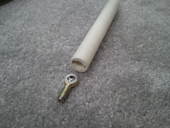
I remembered reading a blog or two talking about how you thread the Heim Joints in without messing the part up. Something to do with PVC Pipe. I had the concept logged in memory and dug it out and decided to take some time and make the tool. Basically, I took a 3/4″ scrap piece of Schedule 40 PVC pipe from my sprinkler redo and a similar length piece of 1/2″ Schedule 40 PVC I stole from a neighbor. I notched the 1/2″ pipe to be just a hair wider than the Heim joints’ flat sections and just deep enough to cover the ball joint portion. Then I used my disk sander to take a little off the outside of the pipe so it would slip into the I.D. of the 3/4″ pipe. I glued them together and then took some time to smooth out the ends and the shank for comfort and part protection. What was left was what I refer to as my Heim Screwdriver. If I got real fancy, I’d throw a bike handlebar grip on it…we’ll see.

That one nutplate was really bugging me…so I went back out to the shop, threaded it in a little ways and then put a little pressure on the head as to apply perpendicular force on it. I figured that riveting the nutplate on may have tweaked it a bit and may have put a little twist on it. With all the material ahead of it in the reinforcement plate and the spar creating a tight tolerance hole, the shaft of the Heim perhaps could simply be unable to fully line up if it was slightly twisted. I am happy to report that this did the trick…whew! I was able to then hand thread the Heim in and no cross threading occurred.Β  I then tested my new tool as well. It appears to be just the ticket for getting these installed.

Trailing Edge Remains

At the conclusion of the build session, I was left with a rudder that has some tight rivets to set and the trailing edge to glue up and then rivet. After that is the front bend and it will be done. I got done just in time to have some pizza with a bunch of family that had stopped by for the Holiday Weekend to attend and participate in a Baby Blessing in the family. Next week looks to be a busy one. Perhaps I will take a break, order a no hole yoke, and figure out the best way to get to those last rivets before knocking out the trailing edge. Until then…Happy Labor Day!

Categories: Rudder

Primed and Ready

September 2nd, 2011 No comments

Waiting for Assembley

It has been a few days since I was last able to work on the Rudder. I was debating what to do on the inside of the skins for primer. As you can see here, I decided to prime it…but VERY lightly. I did not scuff the major portions and lightly misted them. I did however scuff and prime the portions that would be mated with another part. Here you can see the end result. They are dried and ready for assembly. I was still early in the night so I clecoed the spar and the lower rib parts together. After that, I closed up shop for the night. Tomorrow should be a big day.

Categories: Rudder

Lot of Scuffing, Nearly Ready for Primer

August 22nd, 2011 No comments

Lot of Work, Few Pictures

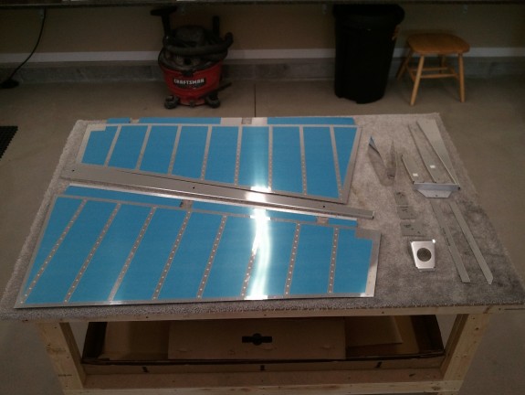
After the crazy productive days in the shop last week, it was time to get the Rudder parts ready for primer. I am still torn about priming the inside of the pristine skins. I have primed where parts interface already and maybe I will simply prime the areas where the spar and the ribs may attach to and then mist the rest. I need to keep the area where the trailing edge AEX free of primer so that the ProSeal will stick.

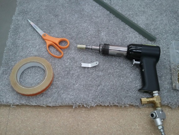
Other than that, I spent some really good time on all the other parts, deburring, dimpling, smoothing, and edge dressing. All that is left is the AEX for the trailing edge and the rudder horn. The rest is ready to be shot with primer and put back together again.
I hope to have a completed Rudder by the end of the week. We’ll see!

Categories: Rudder

Stiffeners Done, On to the Substructure!

August 20th, 2011 No comments

Sub Structure Work Begins

With the stiffeners now complete and riveted onto the skin, it was time to move onto the skeleton of the rudder. Here you see the spar, ribs, re-enforcement plates, counter balance, and rudder horn clecoed together. This was after the top and counterbalance ribs were fluted straight. The structure is then match drilled to #30 and the counterbalance skin is match drilled to #40. Again…the precision of the pre-punched kits really shines through. It simply lines right up.

I think this Part is Important in a Spin!

Here you can see one of the important parts of the plane. It is the rudder control horn. Cables will attach to the outboard ends and then run up to the rudder pedals in the cockpit. The 3/8ths holes is for one of the ball joints that will make up a pivot point of the rudder. It took a little love and filing and Scotchbrite wheeling to get it to nestle in with the rib above, but it turned out a great fit. One of the parts that Van’s has you fabricate is a shim that fits under this horn so that you can tie the horn, spar, and the rib together all fitting at the same level. It was pretty easy to make out of 0.032″ sheet stock.

Fairing Strip Fabrication

Here you see the rudder nearly completely assembled and clecoed together. The substructure is complete, the Rudder horn reinforcement is in and drilled, and at this stage I am fabricating the other two parts Van’s makes you create. These little strips of sheet stock will be what holds the lower fiberglass fairing onto the rudder. A few simple cuts and you match drill to the rest of the already assembled parts.

Good Edge Distance Here

One of the more challenging parts of assembling the rudder is this reinforcement part. First, you have to cut some sizable ears off of it using the standard practice of trimming to the center of the guide holes Van’s pre-drills in the part. Some have found that it is difficult to do this and still retain good edge distance for the holes. Either I am lucky, or Van’s has improved the part because I trimmed to the center and then installed and match drilled and it came out with some room to spare. Here you can see that I have good edge distance and the part clears the web of the adjoining rib. Whew. I have also heard that they used to make you bend this part to the shape they now ship it as. Man am I glad…cause that would have been a bear.

Looking Like Something

After all the fabrication of parts and assembly it was time for all the remaining match drilling. I was able to get it done in short order. The one thing to remember on the rudder is that the trailing edge is NOT drilled perpendicular to the skin but IS drilled perpendicular to the cord. Careful attention however helps and avoids to much trouble as the AEX wedge is pre-drilled to the right angle and helps align the bit as you are match drilling the parts. Still remember not to fight the flow of the bit.

Another View of the Prepped Rudder

Here is another view of the rudder match drilled and ready to…take all apart again. Just whenΒ  you think you got something, you have to tear it down and do a TON more work. It is fun to show the kids though…”look at the size of this!!!” I love it when my kids reply, “WOW, that is soooo cool!” Motivation for sure.

After all That Work...Torn Down for Paint and More Prep

It got late in the evening by the time I was done match drilling the rudder. So I tore it all down and got everything ready to finish all the prep before paint and turned out the lights. Here is where the Rudder stood once it was all said and done. All in all…a great build session. Thanks for the shop pass Dear!

Categories: Rudder

Backriveting…Step by Step

August 20th, 2011 No comments

My Back Rivet Set and Other Tools of the Trick

It’s Saturday and my Honey-Do’s are done…so off to the shop for another good and healthy build session. For some reason, I felt inspired to do a back rivet tutorial. Maybe it will be useful to someone else down the road. So here goes. There are some key tools that are needed to do back riveting correctly.

  1. Rivet Gun
  2. Back Rivet Set
  3. Back Rivet Plate
  4. Rivet Tape

As you can see here, I have my tools for back riveting in place. My back rivet set has a brass collar. I have seen others with a Delrin collar. Before I got started, I polished my collar to a smooth finish both on the sides and the face to reduce the chance of it marring my parts. I made sure to remove the sharp edge of the collar on the inside and outside radius. Turns out that was a good thing. I also lubed the collar and spring up with some dry lube called White Lightning typically used in Cycle lube. It is good stuff and won’t get all over stuff when the tool is in use.

My back rivet plate (not shown) is a 12″ x 4″ x 1/4″ piece of cold rolled steel bar stock a machinist friend gave me. I simply took some Harbor Freight Aviation Department metal finishing abrasive wheels and got one face finished to a mirror. It is hard and heavy and works well.

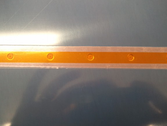
The Rivet Tape is Avery Tools version. The outside edges of the tape are adhesive, while the center portion that goes over the rivet head is not. I like it.

Lay in a Row of Rivets

Step 1, lay your row of rivets into the dimples on the outside part.

Avery Rivet Tape them In

Taped in and Ready

Step 2, place your rivet tape over the heads to hold them in place and to protect the heads from the back rivet plate. Here you can see my back rivet plate on my bench.

Ready for Part on other Side

Step 3, flip the part over and set over the back rivet plate. Ready the part to be joined.

Stiffener in Place over Back Rivet Plate

Step 4, Stack all the parts over the back rivet plate. You can see that I used the carpet on my bench to keep the skin the same level as the back rivet plate. Here you can also see the skin, rivet tails, stiffener all lined up and ready to smack.

Rivets Smashed and Stiffener in Place

Step 5, Smack the heads with your back rivet set. The key here is to make sure the rivet you are setting is on the back rivet plate…otherwise you will make a mess. You can see here that my back rivet set left some marks in the primer. I am sure that they would be far worse if I had not polished the collar. As it stands, they are superficial and a light dusting of primer will cover them nicely.

This concludes your photo Back Rivet tutorial, now back to regular programming.

Categories: Rudder