Left Leading Edge Prep

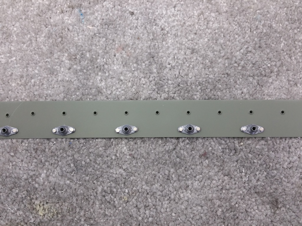
Splice Strip Fabrication Complete
With the tanks now fully sealed, it’s time to get back to finishing up the major wing portions. First up is prepping the splice strips, which hold the tank to the leading edges, dimpled, nut plates attached, and primed. I dimpled the screw holes first, then clecoed on the platenut. Once lined up to my satisfaction, I drilled one ear of each platenut and then clecoed through each drilled hole. I was then able to drill the other ear and remove the platenuts, debur, and then dimple the all the #40 holes. It was good to get back to part fabrication after the tanks. Stuff moves soooo much faster without all that sealant business. I did have to remember what tools I had in the shop though. Since the center holes are already dimpled for the screw, it’s very hard to use standard dimple dies for doing the platenut mounting holes as you could smash the screw dimple back unless…you have a small diameter female dimple die from Cleaveland Tool…which I do. I just had to remember I did after a short panic of the “oh no, how will I get these” moment. I also dimpled the ears of each platenut for a perfect fit.
Splice Strip Art
Once all the holes were properly dimpled, I primed both strips and then cleaned up the shop a bit. Once dry, I proceeded to rivet on the platenuts. I found using the pneumatic squeezer to be very therapeutic.
Left Leading Edge Final Assembly Begins
After the leading edge splice strips were done, I removed the left leading edge assembly off the spar/stand. I then went about prepping the parts for the Stall Warning kit that my wing shipped with. For older (I use the term loosely here) kits, Van’s makes this an option for builders to retrofit. My wings are still new enough that it’s standard. I will be installing an Angle of Attack indication system, but since it’s included, I will add this other “safety feature” as well. You can’t have too many ways for the plane to tell you that you’re approaching a stall, can you?
I removed the doubler from the skin, which I had added a long time ago from the kit parts. I had match drilled it way back when I installed it. I deburred and then dimpled it, much like the splice strips, to mount the platenuts and where it will be attached to the skin. Primed it, then moved on to disassembling the remaining parts of the leading edge. Once dry, I installed the platenuts and then for some reason, clecoed it back onto the skin.
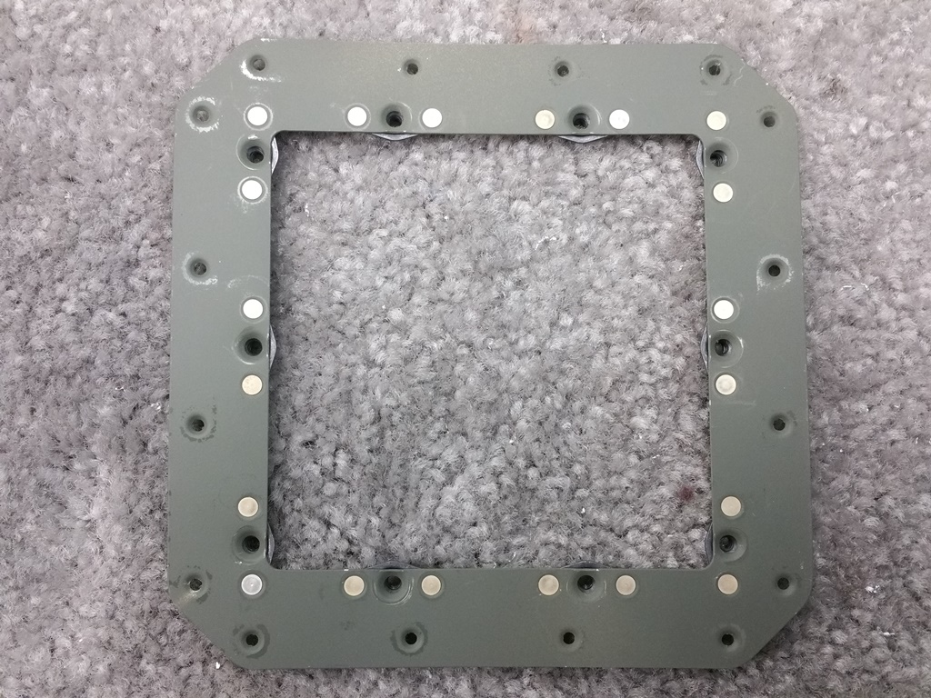
Stall Warner Access Hole Doubler
Once I realized it had to come off again, I removed it, leaving some primer on the skin. It won’t make a difference once final riveted onto the skin in the end.
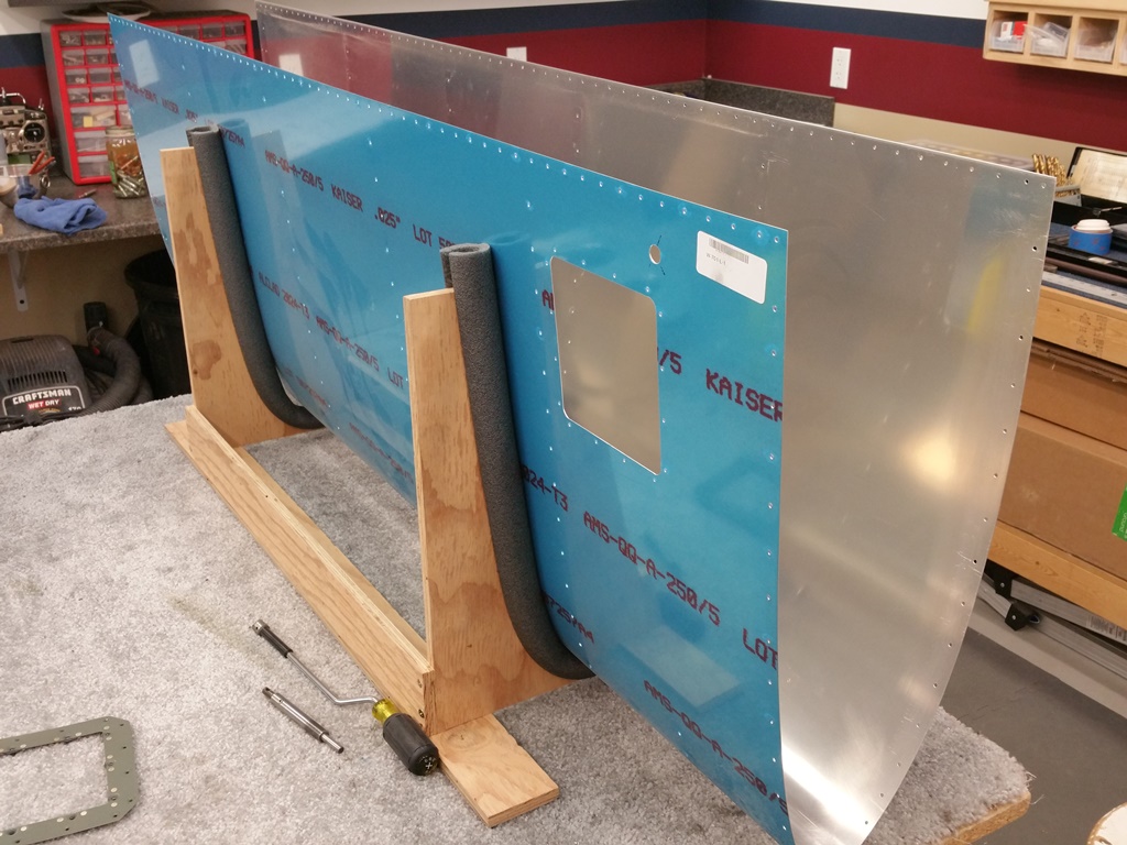
Back to Just Metal Work
Here is the skin in the cradle. I need to remove the vinyl from at least the rivet lines, debur, and then dimple. Once there, will scuff, prime, and then be ready to final rivet. What you can’t see in this photo is the slot that is drilled and cut for the stall warning metal vane that sticks out from the leading edge. I final drilled and connected the holes that where already pre-punched.
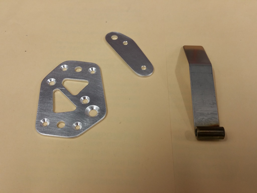
Prepping Stall Warner Parts
I was on a roll for the day…so I prepped the parts for the warning micro-switch cage. You have to countersink for several screws and rivets. I also had to clean up the vane some…as it was roughly welded and had some sharp bits still attached on it. It’s made of stainless steel, so it took some good filing to get it right. Once all the aluminum parts were prepped and ready, I shot them with primer.

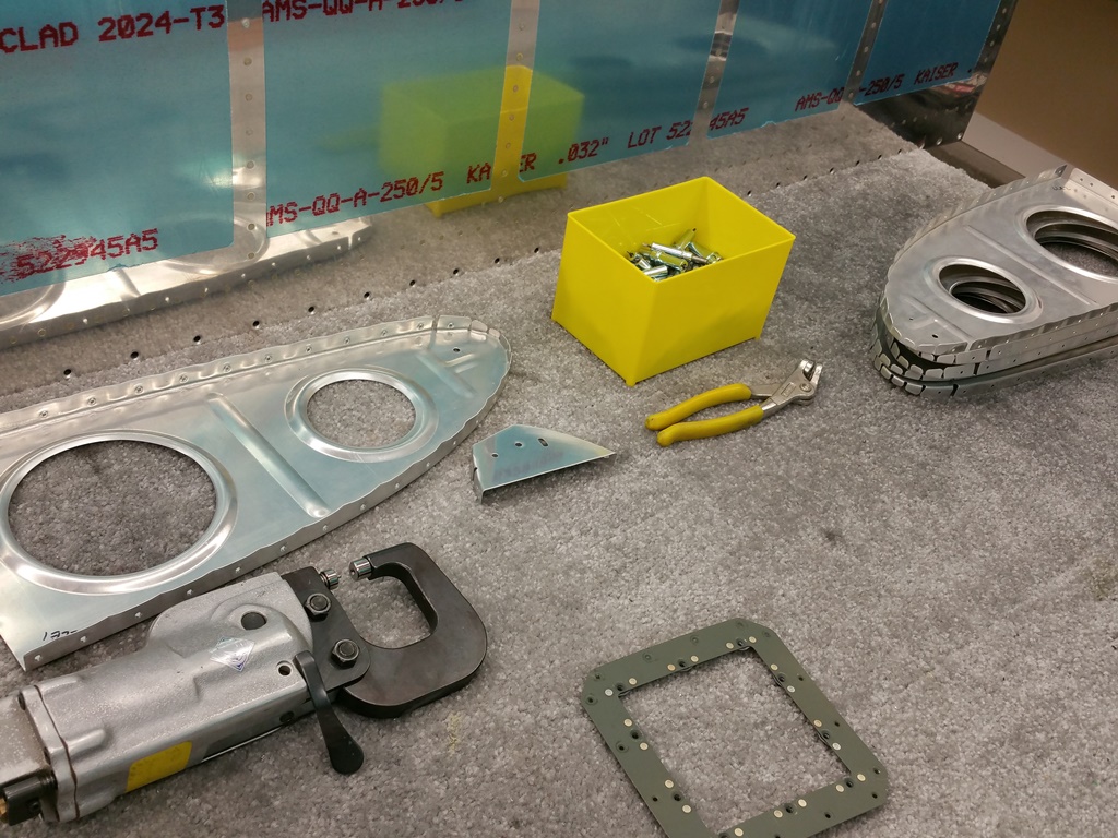
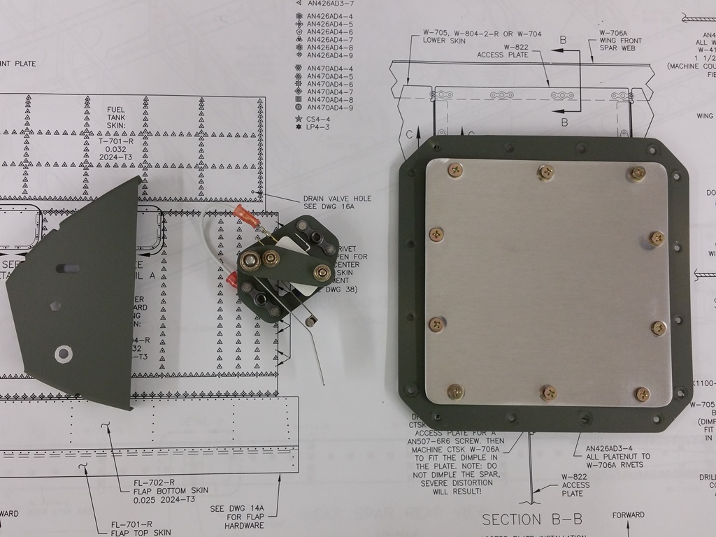
Stall Warning Assembly
Here is a shot of all the parts of the Stall Warning assembly together. I will be riveting in the nose rib along with all the other ribs when the time arrives, but as it stands, the subassembly is done and ready to go in the wing. I presume that the vane will rest on the bottom of the slot in its resting state, as there is NO other stop, other than the rivet head just below it for the platenut that stops its travel down. I don’t recall that being the case on those flying/finished aircraft, but I could have missed it. It will take some adjustment to get it right and working when flying, so we’ll see how all that works later.
Stall Warner Kit Prepped and Ready
Once all the parts were ready to go in final, I called it a night. You can see in the above picture, I did leave the primer off around the lower hole. That’s intentional, so as to give the ground lead from the switch a good, clean contact. Next up is the deburring and dimpling of the full left leading edge skins and ribs. Then final assembly and install permanently onto the wing. Nice to make a post NOT about the tanks!


