Archive

Archive for the ‘Major Wing Sections’ Category

Service Bulletin 16-03-28

May 21st, 2016 No comments
Right Wing Doublers

Right Wing Doublers

As one can clearly see, it has been some time since the last log entry again. However, it turns out that the “slow build” has proven OK at times. Van’s Aircraft recently released another Service Bulletin. The last one they issued is required on a completed assembly (horizontal stabilizer) and I still need to accomplish it. This new one is on the wings, which in my case, are still very much open. I decided that for the $10.00 in parts, I’d get them in the shop and see what can be done to incorporate the fix into my “in progress” wings now.

Left Wing Doublers

Left Wing Doublers

Van’s did mention in the SB that accomplishing as a “preventative measure” is not recommended on “wings that have been fully assembled” but as we know, mine are far from the “fully assembled” stage this point. That said, once getting the parts separated and deburred and cleco’d in place, it’s clear that a good re-write of the order of assembly is required, even for the new wing builders. If you follow the current order on the plans, you won’t be able to get two bottom skin rivets installed (see above picture) and perhaps not be able to set one rivet on the aileron gap fairing nearest the doublers now added. I “think” if you replaced the respective rivets with “cherry max” type pulled rivets, you could actually get the doublers in place with little impact to the build order. I will have to let it sit perhaps until Van’s shows us “new” wing builders how it should be done.

Categories: Major Wing Sections

Placarded Wing Stands

October 24th, 2012 No comments

Just to be Clear

Originally when I thought out my wing stands, I thought that I would paint them red and green corresponding to the NAV lights on each, to differentiate between the 2 wings. Since my neighbor graciously painted them for free at his shop…I took what I got and was happy to do so.

So to get the same effect, I had my other neighbor with a vinyl cutter, make me some placards that could be used instead of paint.

Nerd question of the day…what is the font from? 🙂

Categories: Major Wing Sections

Tie Down Stop Options

September 19th, 2012 No comments

Set Screws for Tie Downs

I placed an order for some set screws to thread into the tie down blocks from McMaster-Carr. The theory is that that set screw sits inside the tie down blocks and remains there. Then as you insert the tie down rings, they hit the set screws and will stop. This allows you to tighten down the tie down rings without crushing the skin since there is a gap between the tie down block and the skin.

I ordered a pack of the above as one option. They are 3/8″ long with a self locking patch on them. This should help them from rotating out of the tie down blocks if I choose to leave the tie down rings out of the plane until needed.

Another Tie Down Option

Another option was to get some smaller set screws and use two of them as jamb screws against each other to keep them from vibrating out. Both are stainless, just like the tie down rings. I have not decided which to use and when I do, I will likely offer the extras to other builders since I have many extras.

Categories: Major Wing Sections

Leading Edges, Joint Plates, Tie Downs Drilled

September 12th, 2012 No comments

Joint Plates Complete

I had more 3/32″ clecos arrive this week, so I could now continue on the leading edges. I assembled the right leading edge parts and set them on the spar. Once on, it was time to tackle the joint plates that are sandwiched in between the inboard rib and the skin. This will tie the tanks and the leading edge assemblies together for a nice transition. I set the rib in place and using some 0.032″ shims made from scratch, centered and clamped the rib into the inboard end. Once in position, I match drilled the flange that attaches to the spar and then clecoed it. Next, I took the joint plate strip and marked a line 1/2″ in from one side. This line should line up with the rivet holes in the skin and leave 11/16″ protruding from the skin for a flange that the tank skins to use as a backer. It took some muscling into place, but I was finally able to get it and the rib where they needed to be. I then drilled the plate and the rib, using the skin as template. Above you can see both done, drilled, and in place.

I then match drilled (actually reamed) all the skin to rib/spars to full size. There are a lot of holes in these wings and I am not even to the tanks yet.

Enlarged the Tie Down Holes

Once all the match reaming was complete, I tackled enlarging the holes for the tie down rings. This means I had to reinstall the large bottom skin to get my previously marked reference lines for the center of the tie down block. This took about a minute to do. Both were just a hair off from the pre-punched reference hole, but Van’s states this is possible and to simply file the hole in the right direction and then enlarge with a unibit. I did just that. This one above on the right wing seems pretty darn close. The left was a hair off, but looking at it, you will never know. If you are looking that close to my plane, you better be a mechanic hired to look at it. 😉

Tie Down Ring Test Fit

Remember those fancy tie-down rings I bought from Cleavland Tool and polished to a mirror shine? I figured now was as good of a time as any to test the fit with the skin. I like it! I will need to buy some threaded inserts from McMaster Carr to set the stop depth of the rings in the tie down blocks like another builder I have seen, but for now…they are looking great!

Both Leading Edges Drilled

By then end of the night, I had both leading edges match drilled.

Next up, Fuel Tanks…yipee! I hear this is the most favorite task of the wings…NOT!

I got the tank parts sorted and on the bench, cleaned up shop, and called it good for the day.

Categories: Major Wing Sections

Leading Edge Cradle Made, Left Leading Edge Started

September 10th, 2012 No comments

Cradle Fabricated

I got home from work and quickly ran over to my neighbor who has a nice table saw and cut down a 2′ x 4′ x 1/2″ sheet of plywood I picked up last Saturday. I ripped it down to 13″ and then cut four 2 1/2″ strips to use as base rails. I then cut the 13″ piece into three 15″ sections (one just in case I messed up). I then traced a leading edge rib and added about 5/16″ to allow for the foam pipe insulation I wanted to use as padding. Once the trace was done I was able to run over to my jig saw and cut out the shape. Per Van’s, I did not worry about making the shape perfect, just close.

I then drilled and screwed the parts together and lined the cradle with the foam pipe insulation. All done, you get what you see above. I was a little concerned about the lower bracing I added to keep the cradle ends upright as it could get in the way of clecoing. Turns out my concerns were unfounded. I had no issues.

Left Leading Edge in Cradle

Here you see the cradle in use. Worked great. I have read that some have had real issues getting the ribs into the leading edge skin. I have even seen some extravagant setups to push the ribs in. I do not know if they have improved the kits or if I was simply lucky, but I had absolutely no issues getting the ribs into the skin. All the holes lined up and looked good. Once I got to this point, it was time to head into the house for dinner and family night.

I did have one issue with the ribs. The nose ribs have several little tabs that help support the skin near the nose. Where the flange near the front ends and the tabs begin on the top in particular, it seems that the transition is not very smooth and when inserted in the skin, causes some little bumps to appear. I read up on VAF on others who had similar problems and their solutions. Basically it comes down to hitting the corners with the scotchbrite wheel and then radiusing the relief notches to eliminate the thin corners that appear after the scotchbriting. I will take some pictures when I get to assembling the right leading edge.

After dinner and family night, I ran back out to the shop, disassembled the left leading edge parts, employed my dressing technique above for adjusting the nose of the ribs. I still had little bulges in the skin where the ribs were a problem. I will likely have a friend of mine that can massage them out come over at some point, but for now, they look much better. The right leading edge should be better.

Left Leading Edge Together

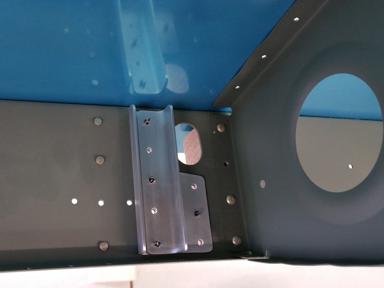
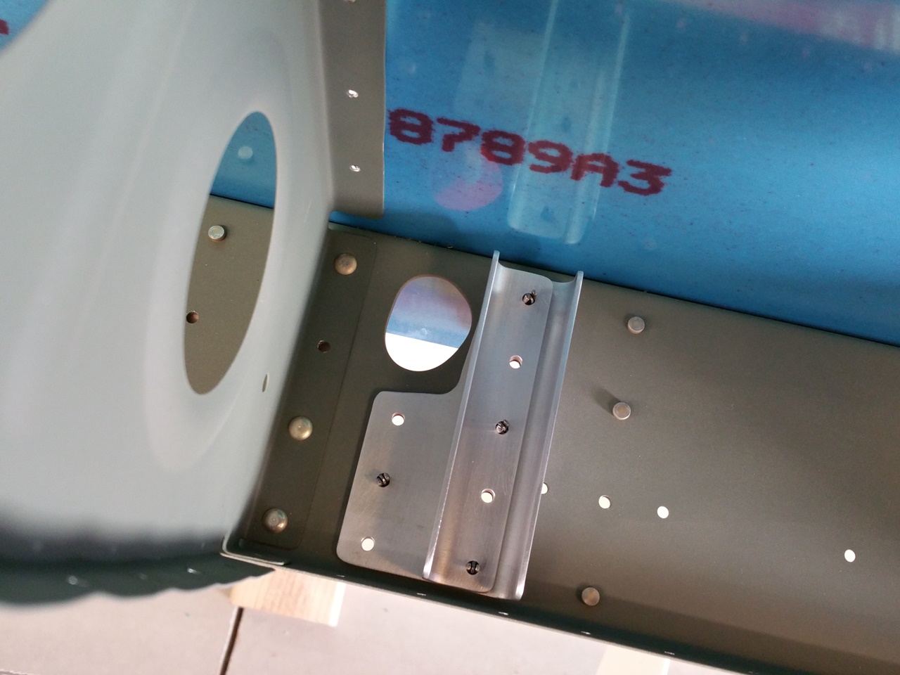
I ran out of clecos after setting the leading edge on the spar. So…I guess that means I am done for the night. I believe that my order to Brown Tool will arrive tomorrow with 200 more 3/32″ clecos and some more #30 and #40 drill bits. That should let me keep going. Before calling it a night, I was able to get the Stall Warner bracket cut from the kit and deburred. I then stole some of the clecos from the wing skins and got it clecoed in place in the nose of the left leading edge. As you see in the above picture, the inspection hole for the Stall Warner system is already cut in the skin. I also clecoed the skin doubler for the inspection hole as well.

I did have some visitors to the shop tonight. A good flying buddy, his son, and dad stopped by. We chatted at bit while I was able to slip the W-408-1L into place, mark the location of the holes, flute, and then slip in back in ready for the W-423 Joint Plate that is to come. I cleaned up the shop and gathered together the other things related to the leading edges (AOA kit, landing light kits) and set them out so I would not forget. It was late, so I called it a night.

Categories: Major Wing Sections

Twist Out, Skins Drilled

September 8th, 2012 No comments

Top Left Skins Drilled

The weekend has arrived and a mix of honey do’s and RV tasks awaited me. I had hung some plumb bobs off the left wing main spar at the inboard and outboard ends the night before. When I went out to the shop in the morning, they were not moving at all. It was time to anchor the rear spar to the newly finished anchor points I had fabricated. I was surprised to see that the distances were only about a 1/16″ off from each other. Not bad. I found an equidistant measurement and anchored each end of the rear spar to that point and checked the level of the main spar again. I then removed and reinstalled the top skins to relieve any pressures caused by the twist removal.

I then hung the plumb bobs on the right wing to repeat the process. Once hung, I headed out to take care of some honey do’s and let the bobs settle. Once done with my list of chores I returned and anchored the right wing.

I then set out to drill the wing skins on both wings. Not much to say other than there are a ton of holes in these wings. I started with the top, then the bottom of the left. I hit each with a #40 chucking reamer.

Bottom Left Skins Match Drilled

On the right wing, I started with the bottom and finished with the top. After that, my back was done for the night. I removed the bottom skins on both wings and set the skins aside. I cleaned up the shop and the chips from the wing structures and then called it a night.

Next up is the outboard leading edge assemblies. I need to make a cradle and debur the ribs a little more. Perhaps that will get done this week. I also realized that I needed more 3/32″ clecos. Those were ordered last week and hopefully will arrive soon.

Categories: Major Wing Sections

Finshed Wing Stand Mount Points

September 6th, 2012 No comments

Fabricated Lower Inboard Hard-points

Since I was able to get the top skins on last night, the wing skeleton was essentially squared up to itself. The pre-punched holes are simply amazing on accuracy and how it lines everything up. With the skeleton now squared up, it was time to make the bottom stand hard points so I can anchor the rear spar in the fixture to take out any twist.

Above is the inboard mount. I used some 2″ angle. Since the distance was a little too much, I had to add a chunk of 3/4″ oak I had laying around. As you can see, it worked out well. Now I can clamp the rear solid at the inboard end.

Fabricated Lower Outboard Hard-points

Now for the outboard end. I used some 1 1/2″ angle. It was too wide to clear the skins protruding from the ribs so I cut some clearance out with the bandsaw. After a little time on the scotchbrite wheel I was able to attach it to the stand.

Nice Little Level

Once the hard points were done, I rechecked the level of the main spars. I picked up this digital level at Home Depot Aviation supply. Between the bubble and the digital scale, I think I have these pretty well zeroed in. The level was pretty well priced for the feature set compared to others out there. Seems pretty accurate.

Time to Square Up and Anchor…Then Drill Away!

Next up, I need to hang some plumb bobs from the main spar and then insure the distance from the string/bob is the same at each end at the rear spar and then anchor the rear spars solid. I think I will then remove the skins to relieve any pressure from the twist removal and then re-attach and start match drilling all the holes.

Categories: Major Wing Sections

Wing Walks Drilled

September 5th, 2012 No comments

Setting up the Doubler for Drilling

I decided to get the wing walk doubler sheets knocked out. For some reason, Van’s ships two 10″ x 48″ x 0.025″ sheets to make these wing walk doublers from. It seems strange that they want you to cut these down to 9 3/8″ x 26″ and then match drill them. Perhaps this contributes to the 51% required to be completed by the builder, or maybe, they just did not feel the need to punch these. Either way, it has to be done. I have read that some builders simply cut the sheets to the 26″ lengths and leave them 10″ wide. I thought about this, but I figured that I would stick to the plan dimensions.

The next question was how to trim these. I called a couple of friends that work with people that do sheet metal work to see if they had a metal shear. After a little more thought, I figured I could just use my shears and cut them close. That is what I ended up doing. I simply measured out the cut marks, sheared them close, and then filed to the line. It took me about three minutes for each of the doublers. I probably saved three or four ounces trimming off the 5/8″ down the side, but every ounce counts…right?

Once the sheets were cut to size, I lined them up per the plans. I then taped them to the underside of the wing skins. It was time to flip and drill. I pulled over my bench that I used to match drill the rudder stiffeners and began to do the same for these holes.

Doubler(s) Drilled

Here you see the end result of the match drilling. It went pretty quick and painless. They are now ready for mounting. Despite being late, I decided to get the doubler and top skins clecoed on to the spars/ribs. Once the skins were on, I cleaned up the shop and called it a night.

Categories: Major Wing Sections

Wings in Stands! Happy Labor Day!

September 3rd, 2012 No comments

Stand Anchored and Wings Hanging

Happy Labor Day! I love working in banking as I get a free week of extra vacation with all the Federal Holidays. I started the day by taking care of the lawn. That took most of the morning. I have to stay on top of the “Honey Do’s” and my son that usually mows the lawn spent the night with his cousin up north and likely would be gone all day. Once the lawn was looking better than the local golf courses ;-), I headed out to the shop.

Big day in the RV Factory. I finished prepping the stands and made the hard choice to just drill my floor and anchor the stands. Once the first hole was drilled, the rest seemed easier to do. I drilled the holes in the corners of the base plates, drilled the floor, dropped in and set the anchors, then bolted the stands down. Once secured, I set the skeletons on the stands. I think I made the right choice, the stands are VERY stiff and secure. These should make for very straight wings.

I set the stands in the middle of the shop and about three feet apart. I figure this should give me plenty of room to get around and between the wings as I work on them. Times like these make me glad I built my shop with good depth.

It was time for dinner so I needed to head off to the grill to burn some patties. Once dinner was complete, I set out to make the center support blocks to take the sag out of the wing structures. They are simply some 2″ x 4″ blocks with some all thread and nuts/washers that can be “micro” adjusted like the stands themselves. All in all, a good day! Now I can start the skin work.

Categories: Major Wing Sections

Wing Stand Work

September 1st, 2012 No comments

No pictures. I simply attacked the now sandblasted, and painted wing stands that my neighbor generously helped me out with. Pays to know a custom auto body painter!

I will likely do a writeup on the stands as I have been asked by several people to describe them. Basically, I ripped off Rudi Greyling from South Africa. I used his design as a starting point and then made some enhancements I thought would make them a bit nicer. I am not sure if the enhancements made them better, but they seem to be sufficient to me.

I added the horizontal angle, all thread, brackets, and hardware. It took most of the day and a few trips to the Lowes Aviation to get the stands to where I needed prior to use. The one remaining question was how would I attach them to the floor?

I have not liked the idea of drilling my brand new shop floor, so I added what I thought would be a solid base so I could perhaps liquid nail the base to the floor and then cut them off and clean up the residue when done. I have seen where some have glued blocks to the floor with success, but not metal stands. I set up a test of some scrap steel and some concrete to see if it would hold. It did not. With little effort, I was able to separate the parts.

I also thought about all the temperature fluctuations my shop sees. I would hate to have my wings in the stands and then come into the shop and see that the cold had caused the adhesive to snap free of the base of the stands and my wing was on the floor.

In the end, I think anchoring the stands to the floors with concrete anchors is the best way to go with the least risks. I plan to finish the floor anyway and when I am filling the expansion joints with the self leveling filler (designed for allowing the flex) I will simply fill these holes too and then epoxy the floor. Once done, you will never know the holes were there. It got late so the anchoring will have to wait until Monday.

Categories: Major Wing Sections

Ribs/Spars Riveted

August 31st, 2012 No comments

Ribs to Spar Assembly Begins

Since the ribs had been primed and dry for a day, I decided that it was time to get out to the shop and get the spars connected together. Above you can see the right wing process starting. Based on advice from other builder sites I have read, it is easier to attach the ribs to the main spar first, then attach the rear spar. This allows you to get the gun on the manufactured head by bending the rib out of the way a little.

Another tip is to start with the third rib out from the root and do the wing walk ribs first. As you can see, the ribs at the root are closer together and trying to get in between them with the gun would be difficult at best. This worked out well and I was able to quickly set the AD4’s with my gun and bucking bar. I also used some Snap-Soc’s from Avery Tools to assist in keep the rivet set on the manufactured head. They work as advertised and I highly recommend them. It took some time to get back into the riveting rhythm since it has been a while since I have had to use a rivet gun. I got it back pretty quick and was able to knock out the main spar rivets pretty quick. I only had to drill out 1 rivet, but it was really bad as the gun had wandered all over the head for some reason.

Once the main spar was done, I attacked the rear spar. I clecoed the spar on and then marked the holes that would not receive rivets now with some tape. This kept me from moving them to another hole and having to drill out extra rivets. The squeezer made quick work of these. One word of caution, do not try and put the manufactured heads on the spar side. It will cause the rib flanges to distort. You may be tempted for aesthetics so they match all the other heads on the spar if you put them in like I did. I also read this on another builder log and I am glad I listened. All mine set nicely.

I did notice that the call outs for rivets may be a little off in the root area of the rear spar. Pay close attention here and if needed, use a little longer than called out and cut them to be right if needed. If you use the rivets called out in the area of the doubler and rib, they will not be in spec. Specifically the W-710,W-711 to W-707A, W-707G, W-707D Rivets called out as AN470AD4-8’s. I used 9’s here and it seemed better…or at least made me feel better in a potentially high stress area like this location is. Measure twice, set once.

Right Wing Riveted

Here you see the right wing ribs and spars together. Starting to look like a plane part.

Root to Tip Line-Up

I had to take another shot with the ribs all attached and primed. I love the precision of this kit.

Skeletons Done

I repeated the process for the left wing and was left with 2 wing skeletons ready to be hung in the assembly stands. Problem is they were not in the shop yet. My neighbor was not done sandblasting and painting them yet. Not bad for an evening’s work. (My office did close early though.)

It was funny, as I was cleaning up my shop for the night, my neighbor kid came over (apparently to eat dinner) and asked, “what’s next?” I replied that I needed the stands her dad is painting for me to move on. Just then, her dad walked into the shop and said…”I have some widgets for you!” Talk about timing. Looks like I have what I need to move on. This should be a good Labor Day Weekend.

Heck…for Posterity Sake

Categories: Major Wing Sections

Ribs Primed

August 30th, 2012 No comments

Primed and Drying

I think my index finger is still numb from the spray cans, but with all the fumes, I am not sure. 🙂 I was able to get the ribs primed and ready for assembly with the spars. Other than the Duplicolor Self Etching Primer cans spitting/dripping in some places, the ribs look great! I really do dig the color. It just seems to scream airplane parts. After living near and touring the USAF Museum at Wright Patterson AFB many times, I just like the green color. Kind of a throw back to the bombers and fighters of WWII.

Left Wing Ribs Drying

Here you can see my cheap but effective priming tables. They are simply chicken wire stretched over a 2″x4″ frame. They work pretty well. I usually will start  priming the parts with the flanges up so that when the part is flipped, the chicken wire only contacts the parts in a few places where they have been primed before. These are the left wing ribs drying.

Right Wing Ribs Drying

Here are the right wing ribs drying on my bench. I will let them sit for a day or so and then start riveting them to the spars. This should be a productive Labor Day weekend!

Categories: Major Wing Sections

Main Ribs Ready for Primer

August 29th, 2012 No comments

Scuffed and Clean, Ready for Primer

I was able to get some work in the shop tonight. I spent the time scuffing the ribs in prep for primer. I hope to shoot the paint on them soon so I can assemble them with the spars over the holiday weekend. Again, the shop computer turns out to be a good asset as the 3rd season of 24 was playing in the background to keep me from focusing on the repetitive nature of the task. Some may wonder how that works, but I do not actually watch the show, I simply listen. Some like music, I like shows. To each his own.

I went through a lot of scotchbrite pads. Then again, there are a lot of ribs, so it makes sense.

Once the scuffing was complete, I wiped each with MEK to clean them. I will hit them once more with MEK before priming them just to make sure I got them all clean.

My body is sore, but the prospect of assembly in the near future is exciting!

Categories: Major Wing Sections